Air supply device for an internal combustion engine

a technology for internal combustion engines and air supply devices, which is applied to liquid fuel engines, machines/engines, mechanical equipment, etc., can solve problems such as unsatisfactory losses, and achieve the effects of facilitating the manufacture of secondary air chargers, simple and inexpensive sealing arrangements, and large tolerances in wheels

Active Publication Date: 2009-04-07
CHEMTRON RES
View PDF17 Cites 10 Cited by
  • Summary
  • Abstract
  • Description
  • Claims
  • Application Information

AI Technical Summary

Benefits of technology

[0006]The compressor wheel and the turbine wheel according to the invention provide for a simple inexpensive sealing arrangement with respect to the housing. There is no longer a radial gap between the blades and the housing and, accordingly, gap losses along the blade structures do not occur. Furthermore, it is advantageous that there are scarcely any critical tolerances to be maintained during the manufacture of the wheels.
[0007]Advantageous embodiments of the compressor wheel and the turbine wheel are provided in particular by an optimum air inflow to the compressor wheel in combination with an air filter element and an air inlet channel. Moreover, the manufacture of the secondary air charger is substantially facilitated because of the absence of the gap problem, as the typical effects of the relatively large tolerances in wheels manufactured from plastics are kept small.

Problems solved by technology

The wheels are disposed in a housing with a radial gap between the wheel blades and the housing, which radial gap results in undesirable losses.

Method used


Image

  • Air supply device for an internal combustion engine
  • Air supply device for an internal combustion engine
  • Air supply device for an internal combustion engine

Examples


Embodiment Construction

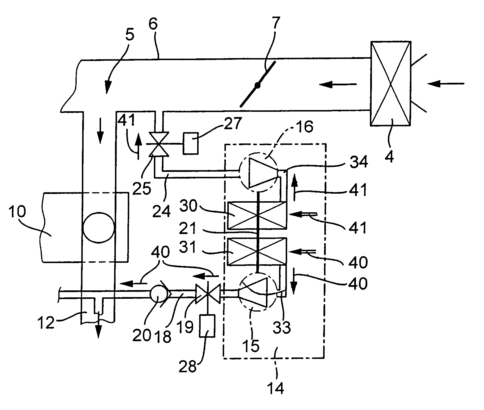
[0025]FIG. 1 shows in a diagrammatically simplified functional illustration a secondary air supply device for an internal combustion engine 10. Air is supplied to the internal combustion engine 10 via an air filter 4, said air passing further into an intake section 5 which comprises an intake manifold 6 and a throttle valve 7. The air which flows from the air filter passes to cylinders (not shown) of the internal combustion engine 10 in a manner which is controlled by the throttle valve 7. The exhaust gases which are emitted by the internal combustion engine 10 pass in a known manner into an exhaust gas region 12 comprising the exhaust manifold and the exhaust gas treatment system. The secondary air supply device has a secondary air charger 14 which is delimited by dash-dotted lines in FIG. 1 and has a compressor 15 and a turbine 16. The compressor 15 supplies air into the exhaust gas region 12 of the internal combustion engine 10 via a secondary air line 18. In the secondary air li...


PUM

PropertyMeasurementUnit
plasticaaaaaaaaaa
pressureaaaaaaaaaa
densityaaaaaaaaaa

Abstract

In a secondary air supply device comprising a turbine and a compressor with turbine and compressor wheels having blades which are covered by wheel covers and an air filter structure disposed between the turbine and compressor wheels, so that air is supplied to the compressor and to the turbine from a common filter structure disposed between the compressor and the turbine wheels.

Description

[0001]This is a Continuation-In-Part Application of International Application PCT / EP2004 / 008325 filed 24 Jul. 2004 and claiming the priority of German Application 103 35 261.9 filed 1 Aug. 2003.BACKGROUND OF THE INVENTION[0002]The invention relates to a secondary air supply device including a compressor and a turbine wheel for an internal combustion engine.[0003]A secondary air supply device with a compressor wheel and a turbine wheel for an internal combustion engine is already known (DE 199 37 781 A1) wherein the compressor and turbine wheels however are configured in an uncovered, conventional design. The wheels are disposed in a housing with a radial gap between the wheel blades and the housing, which radial gap results in undesirable losses.[0004]It is the object of the present invention to provide a more efficient secondary air supply device.SUMMARY OF THE INVENTION[0005]In a secondary air supply device comprising a turbine and a compressor with turbine and compressor wheels h...

Claims


Application Information

Patent Timeline
Patent Type & Authority Patents(United States)
IPC IPC(8): F01N3/00F01N3/32F02C1/02F02D9/02F04D29/02F04D29/28F04D29/70
CPCF01N3/32F02C1/02F04D29/023F04D29/284F04D29/70F02D2009/0283Y02T10/20F05D2220/40F05D2300/43F05D2300/12F05D2300/433F05D2300/603F05D2300/436F05D2300/17Y02T10/12
Inventor LEHMANN, HANS-GEORGSCHLEGL, MARTINSTARK, HOLGER
Owner CHEMTRON RES
Why Eureka
Try Eureka