
Method of, and apparatus for, manufacturing organic EL device; organic EL device; electronic device; and liquid droplet ejection apparatus

a technology of organic el and manufacturing method, which is applied in the direction of solid-state devices, metallic material coating processes, printing, etc., can solve the problems of cracks, deterioration in the like, and achieve the effect of accelerating the quality of light-emitting materials, cracks, and the lik

Inactive Publication Date: 2009-04-14
TOKYO ELECTRON LTD
View PDF58 Cites 23 Cited by
  • Summary
  • Abstract
  • Description
  • Claims
  • Application Information

AI Technical Summary

Benefits of technology

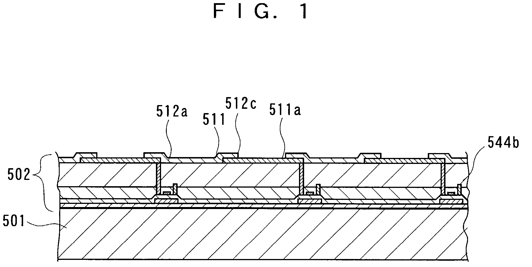
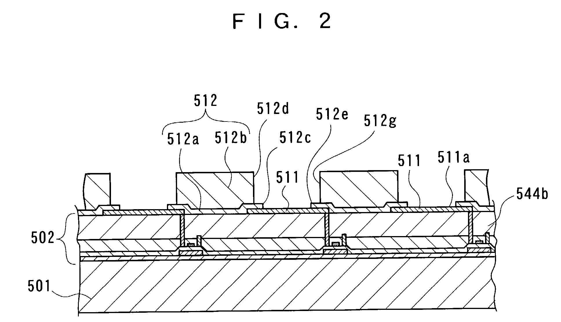
[0009]According to this arrangement, since the step of selectively ejecting the light emitting function material to the substrate is performed in the atmosphere of an inert gas, the light emitting function material can be kept out of contact with the open air (outside air) in the course between the ejection of the light emitting function material to the formation of the organic EL function layer. Therefore, the deterioration in quality of, or damage to, the light emitting function material can be prevented.
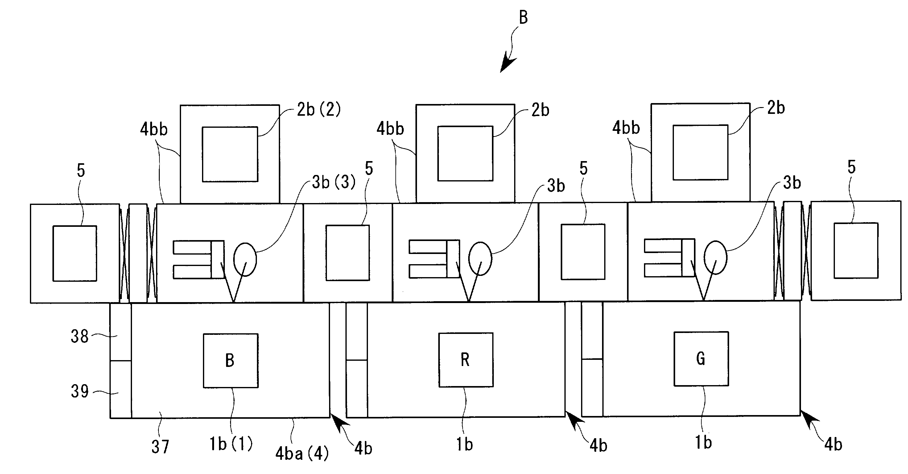
[0064]According to this arrangement, since the liquid droplet ejection means is housed inside the chamber means constituting the atmosphere of an inert gas, the ejection of the function material by the liquid droplet ejection means is carried out inside the atmosphere of the inert gas. Therefore, in the course from the ejection of the function material to the forming of the function film (layer), the contact of the function material with the open air is eliminated. Even a material that is likely to be damaged in the open air can be prevented from being changed in quality or from being damaged.

Problems solved by technology

In the above-described conventional apparatus for manufacturing an organic EL device using the function liquid droplet ejection head, if a material which is liable to react with oxygen, or the like, in the open air (outside air) is used as the light emitting material, there is the following problem.
As a result, deterioration in quality of the light emitting material is likely to be accelerated.
In addition, there is another problem in that the light emitting material that has been adhered to a target reacts with oxygen, or the like, whereby cracks, or the like, are likely to occur in the course of drying.

Method used


Image

  • Method of, and apparatus for, manufacturing organic EL device; organic EL device; electronic device; and liquid droplet ejection apparatus
  • Method of, and apparatus for, manufacturing organic EL device; organic EL device; electronic device; and liquid droplet ejection apparatus
  • Method of, and apparatus for, manufacturing organic EL device; organic EL device; electronic device; and liquid droplet ejection apparatus

Examples


Embodiment Construction

[0137]With reference to the accompanied drawings, a detailed description will now be made about preferred embodiments of this invention. An ink jet head of an ink jet printer (the ink jet head is also referred to as a liquid droplet ejection head) is capable of ejecting very minute ink droplets (liquid droplets) in the form of dots at a high accuracy. Therefore, it is expected to apply the liquid droplet ejection head to the field of manufacturing various kinds of parts by using, as the liquid droplet (liquid to be ejected), special inks, light emitting or photosensitive resins, or the like.

[0138]An apparatus for manufacturing an organic electroluminescent (EL) device according to this embodiment is to be built into a manufacturing line for manufacturing an organic EL device which is a kind of so-called flat display device. In the apparatus in question, a function liquid such as a light emitting material, or the like, is ejected from ejection heads of a plurality of function liquid ...


PUM

PropertyMeasurementUnit
Temperatureaaaaaaaaaa
Fractionaaaaaaaaaa
Temperatureaaaaaaaaaa

Abstract

An organic EL function layer is formed in the following manner. Namely, relative scanning is carried out between a substrate and a function liquid droplet ejection head having introduced therein a light function material is selectively ejected toward the emitting function material. The light emitting substrate such that an organic EL function layer is formed on a multiplicity of pixel regions on the substrate. The work of ejecting the light emitting function material is carried out in an atmosphere of an inert gas.

Description

BACKGROUND OF THE INVENTION[0001]1. Field of the Invention[0002]This invention relates to an apparatus for, and a method of, manufacturing an organic electroluminescent (EL) device in which a function liquid droplet ejection head as represented by an ink jet head is used, an organic EL device, an electronic device, and a liquid droplet ejection apparatus.[0003]2. Description of Related Art[0004]This kind of conventional apparatus for, and a method of, manufacturing an organic EL device in which a function liquid droplet ejection head as represented by an ink jet head is used is still under development for putting it into practical use. In such a conventional apparatus, a light emitting layer is formed in the following manner. Namely, a light emitting material in a liquid state is introduced as a function liquid into a function liquid droplet ejection head. The light emitting material is then ejected to a multiplicity of pigment regions. Solvent in the light emitting material is ther...

Claims


Application Information

Patent Timeline
IPC IPC(8): B05D5/06B05D1/38B05D3/02B41J2/01B41J2/145B41M3/00H01L27/32H01L51/00H01L51/40H01L51/50H01L51/56H05B33/10
CPCB41J2/145B41M3/006H01L51/0005B41J2202/09H01L51/56H01L27/3244H01L27/3295H01L27/3211H10K59/35H10K59/122H10K71/135H05B33/10H10K59/12H10K71/00
Inventor HAYASHI, TAKAYUKI
Owner TOKYO ELECTRON LTD
Learn More