Method of producing self-aligned mask in conjunction with blocking mask, articles produced by same and composition for same

a self-aligning and mask technology, applied in the field of patterns, can solve the problems of reducing the effective dielectric constant, reducing the accuracy of the mask, and reducing the cost of typical procedures used to generate the mask by lithographic or other means, and achieves the effects of low cost, high precision and accuracy

Inactive Publication Date: 2009-04-14
IBM CORP
View PDF3 Cites 11 Cited by
  • Summary
  • Abstract
  • Description
  • Claims
  • Application Information

AI Technical Summary

Benefits of technology

[0020]The present invention enables the production of patterns on a substrate having regions with different chemical identities and provides efficient methods of producing fine patterns on substrates on which electronic devices used in the microelectronics industry can be fabricated.
[0022]The patterns can be fabricated with great precision, accuracy and at low cost, without the use of typical high-resolution lithography reticles and without the use of lithography that typically requires high-resolution overlay of a mask pattern to a substrate having a pre-patterned film thereon.

Problems solved by technology

Unfortunately, typical procedures used to generate a mask by lithographic or other means can be expensive and error prone particularly when alignment or overlay is required.
Both of these approaches reduce the effective dielectric constant, keff, of the components between metal lines and as a result, interconnect signals travel faster through conductors due to a reduction in resistance-capacitance (RC) delays.
Unfortunately, these strategies are difficult to implement due to limitations in maintaining sufficient properties, i.e., mechanical, barrier, electrical, etc., that result when there is a reduction in thickness or changes in the chemistry of the layers.

Method used


Image

  • Method of producing self-aligned mask in conjunction with blocking mask, articles produced by same and composition for same
  • Method of producing self-aligned mask in conjunction with blocking mask, articles produced by same and composition for same
  • Method of producing self-aligned mask in conjunction with blocking mask, articles produced by same and composition for same

Examples


Embodiment Construction

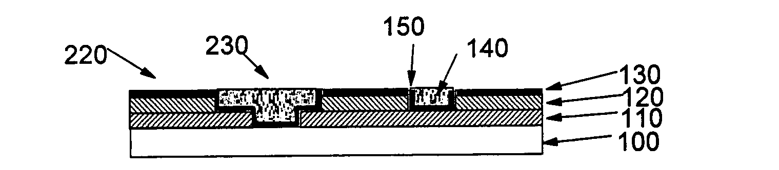
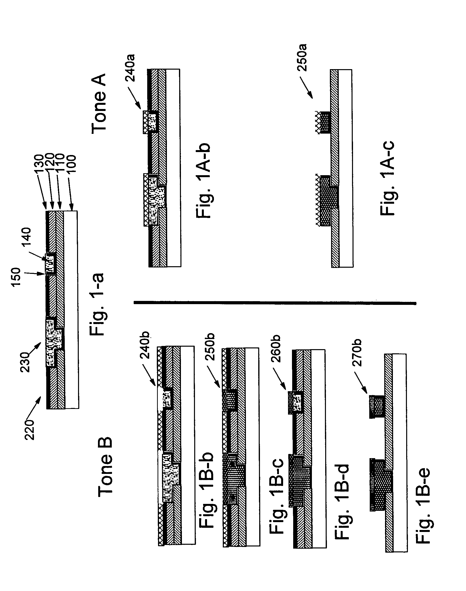
[0042]The present invention provides a method of forming a patterned layer on a substrate having thereon a pre-patterned film. The method includes the steps of: applying onto the substrate having thereon a pre-patterned film a solution of a masking material in a carrier; removing at least a portion of the carrier to form a coating; patternwise exposing the coating to radiation in conjunction with a blocking mask pattern so that the radiation that is passed through the blocking mask is transmitted through the coating and is reflected back to the coating to produce a latent image in the layer having exposed and unexposed regions with a given spatial intensity distribution commensurate with the convolution of the block mask pattern and the spatial reflectivity map of the substrate having thereon a pre-patterned film; and developing the exposed coating to reveal a mask pattern in the coating commensurate with the spatial intensity distribution generated during exposure to radiation; and...


PUM

PropertyMeasurementUnit
exposure wavelengthaaaaaaaaaa
feature sizeaaaaaaaaaa

Abstract

A method of forming a self aligned pattern on an existing pattern on a substrate including applying a coating of a solution containing a masking material in a carrier, the masking material being either photo or thermally sensitive; performing a blanket exposure of the substrate; and allowing at least a portion of the masking material to preferentially develop in a fashion that replicates the existing pattern of the substrate. The existing pattern includes a first set of regions of the substrate having a first reflectivity and a second set of regions of the substrate having a second reflectivity different from the first composition. The first set of regions can include one or more metal elements and the second set of regions can include one or more dielectrics. Structures made in accordance with the method. A low resolution mask is used to block out regions over the substrate. Additionally, the resist can be applied over another masking layer that contains a separate pattern.

Description

BACKGROUND OF THE INVENTION[0001]1. Field of the Invention[0002]This invention relates to the production of patterns on a substrate having regions with different chemical identities. More particularly, it relates to a method of producing fine patterns on substrates used in, for example, the microelectronics industry on which electronic devices are fabricated. The present invention also relates to devices fabricated in accordance with these methods.[0003]2. Description of the Related Art[0004]A number of applications and technologies involve structures having a well-defined arrangement of distinct regions. Normally, these structures are defined by patterning processes such as lithography, embossing, and stamping, and have length scales ranging from nanometers to several microns to even millimeters. In many of these systems it may be necessary or beneficial to apply an additional component or treatment to or above only a subset of the chemically district regions. One commonly used tec...

Claims


Application Information

Patent Timeline
Patent Type & Authority Patents(United States)
IPC IPC(8): G03F7/00G03F7/20
CPCG03F7/2022
Inventor COLBURN, MATTHEW ENITTA, SATYANARAYANA VPURUSHOTHAMAN, SAMPATH
Owner IBM CORP
Why Eureka
Try Eureka