Hearing aid circuit reducing feedback

a hearing aid and circuit technology, applied in the field of hearing aid circuits, can solve the problems of unsatisfactory effects, inconvenient fitting of hearing aids, and inability to meet the needs of hearing aids,

Active Publication Date: 2009-04-14
INTRICON INC
View PDF11 Cites 52 Cited by
  • Summary
  • Abstract
  • Description
  • Claims
  • Application Information

AI Technical Summary

Problems solved by technology

These expedients are often unsatisfactory solutions since the forward gain is desired and a tighter fitting hearing aid is less comfortable.
In many other circumstances, however, the LMS algorithm does not work properly.
The result of this correlation is that the LMS algorithm adjusts the FIR filter to reduce the input signal, which in turn results in a misadjusted FIR filter.
The LMS algorithm doesn't differentiate between correlation from an environmental sound and correlation from hearing aid feedback.
If the FIR filter becomes sufficiently misadjusted then a true feedback oscillation will begin to build resulting in a very annoying artifact.
This problem with the LMS algorithm has been known for a long time and attempts have been made to try to mitigate the problem.
The weakness of this attempt is that there is poor or no compensation for real time changes in the feedback that occur from common situations such as jaw motion or a telephone being brought near the ear.
This, however, also limits the range of correction that is possible.
This works if the noise has a high enough amplitude, but adding noise is annoying to a hearing aid user.
The problem with this attempt is that it requires the delay to change more rapidly than the FIR is corrected and for the phase to be changed by at least 180 degrees, typically more than 360 degrees.
In practical situations this large rapid phase change results in a sound artifact that is undesirable.
Such fast internal feedback correction could not be used in the PRIOR ART arrangement in FIG. 1 without distorting the environmental sounds.
This typically means that either the adaptation must occur slower than desired or that the varying delay occurs so fast that it produces undesirable noticeable artifacts.
As mentioned above, this uncertainty has been a weakness in the prior use of LMS algorithms.
The problem with the conventional algorithms is that typically 360 degrees or more shift is needed.
Note that the β can be obtained even when the true signal source is sinusoidal, something that is not possible with any of the normal LMS designs.
This design is preferred over the first example because it is a simpler filter design, but it has the disadvantage that it is not organized into specific frequency bands.

Method used


Image

  • Hearing aid circuit reducing feedback
  • Hearing aid circuit reducing feedback
  • Hearing aid circuit reducing feedback

Examples


first embodiment

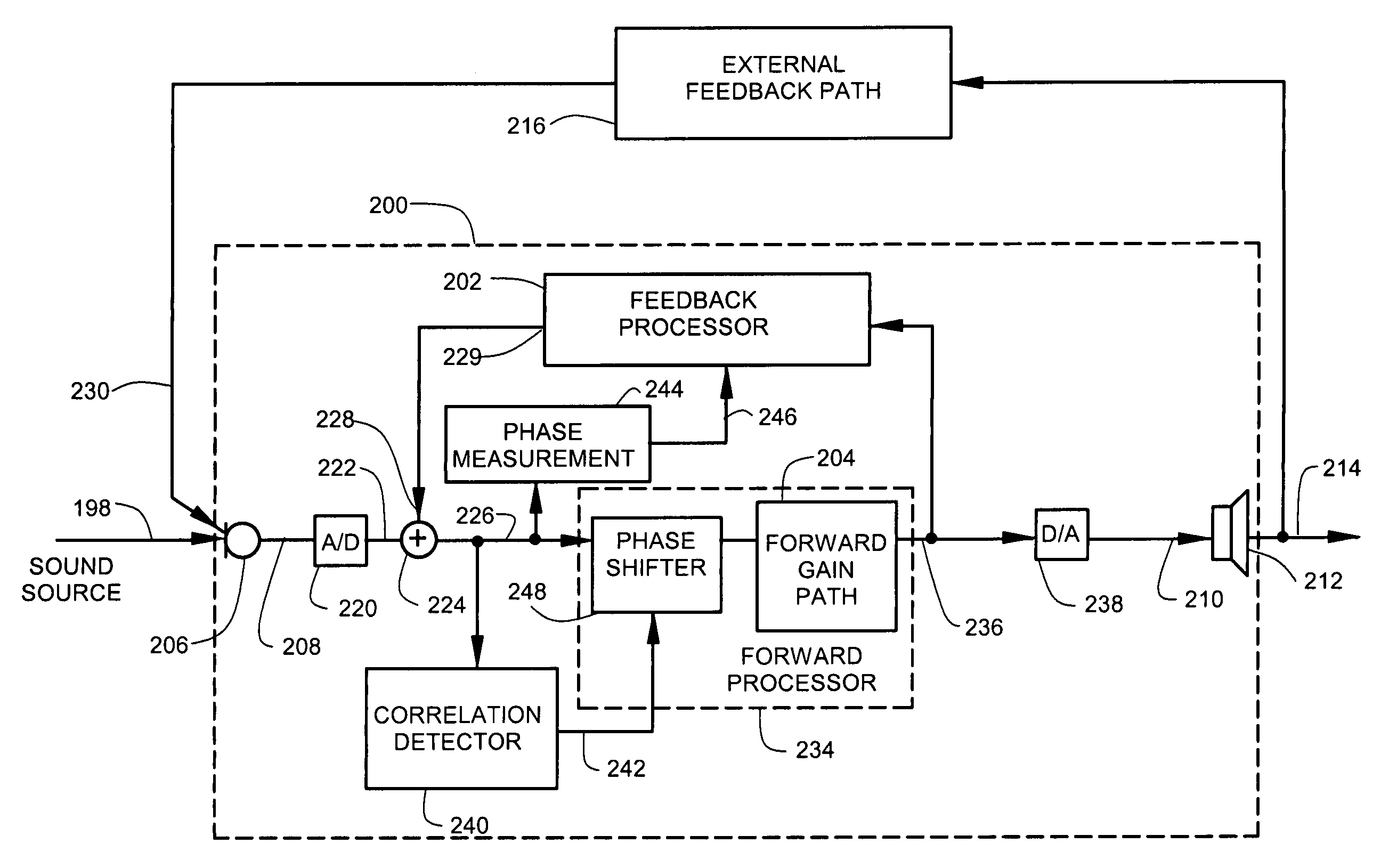
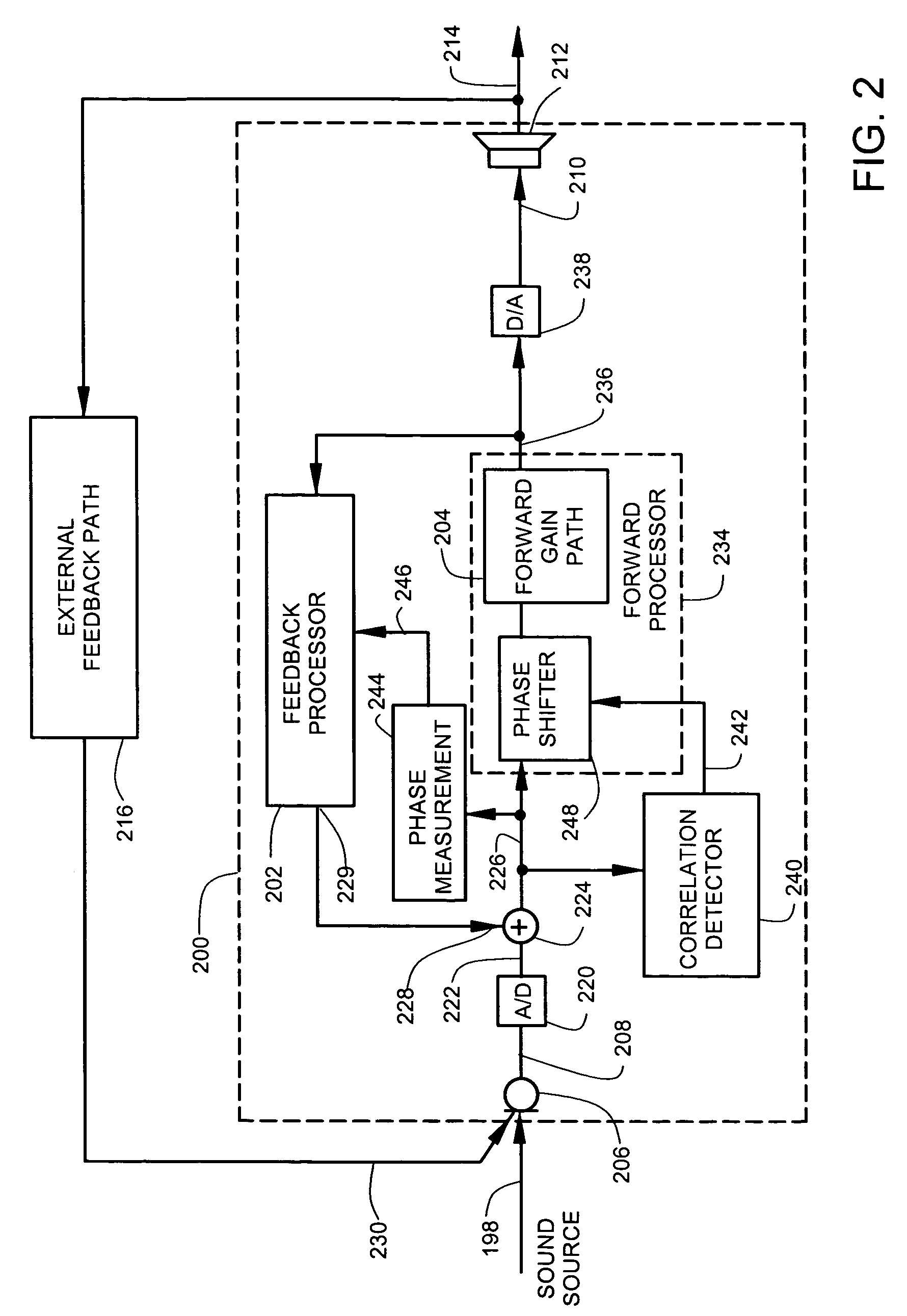
[0033]FIG. 2 illustrates a block diagram of a hearing aid circuit 200 that includes an adjustable internal feedback path controlled by a small phase shift measurement (SPM) algorithm. The SPM algorithm is able to differentiate true hearing aid feedback from highly correlated sounds from the environment. The SPM algorithm provide fast internal feedback correction for hearing aid feedback without distorting highly correlated environmental sounds. Such fast internal feedback correction could not be used in the PRIOR ART arrangement in FIG. 1 without distorting the environmental sounds. The arrangement shown in FIG. 2 provides the user with a desired range of amplified environmental sounds without the disadvantages of high hearing aid feedback and distortion.

[0034]The hearing aid circuit 200 provides amplification along a feedforward path 234 in an environment that is subject to external audio feedback path 216. A correlation detector 240 detects correlation at a feedforward path input ...

second embodiment

[0050]FIG. 5 illustrates a block diagram of a second embodiment that includes an SPM algorithm. This embodiment uses very simple circuit elements. The correlation detector 540 and the phase measurement circuit 544 are modification of standard LMS elements. The phase shifter 248 is implemented with a small variable delay.

[0051]The hearing aid circuit 500 provides amplification along a feedforward path 534 in an environment that is subject to an external audio feedback path 516. A correlation detector 540 (which is combined with a phase measurement circuit 544) detects correlation at a feedforward path input 526 and generates a correlation output 542. A variable delay phase shifter 548 receives the correlation output 542. The variable delay phase shifter 548 introduces a phase shift along the forward path 534 as a function of the correlation output 542. In a preferred arrangement, the phase shift has a non-interfering amplitude that is small enough to be imperceptible to the user.

[005...

third embodiment

[0069]FIG. 8 illustrates a block diagram of a hearing aid circuit 400 that includes an adjustable internal feedback path controlled by an SPM algorithm. The hearing aid circuit 400 is preferably realized using a Toccata digital signal processor available from dspfactory, Ltd., 611 Kumpf Drive, Unit 200, Waterloo, Ontario, N2VIK8, Canada. Other digital signal processors can be used as well.

[0070]The hearing aid circuit 400 comprises a summing circuit 424 that receives an audio output 422. The audio output 422 includes audio from a sound source 398 and audio from audio feedback 430 received from a receiver via an external feedback path (not illustrated). The summing circuit 424 also has a second summing input 428 and a net sum output 426.

[0071]A forward processor 434 receives the net sum output 426 and provides a processed output (feedforward output) 436. The forward processor 434 includes a Weighted Overlap-Add (WOLA) analyzer 450 that receives the net sum output 426. The WOLA analyz...


PUM


Abstract

A hearing aid circuit includes a correlation detector that detects correlation at a feedforward path input and that provides a correlation output to a phase shifter. The phase shifter introduces a phase shift along a feedforward path. A phase measurement circuit measures a phase shift at a feedforward path input, and provides a phase measurement output to an internal feedback processor. The internal feedback processor adjusts internal feedback as a function of the phase measurement to suppress coupling of external audio feedback along the feedforward path.

Description

CROSS-REFERENCE TO RELATED APPLICATION[0001]This application claims the benefit of U.S. Provisional Application 60 / 499,755 filed on Sep. 3, 2003 for inventor Robert J. Fretz and entitled Feedback Cancellation.FIELD OF THE INVENTION[0002]The present invention relates generally to hearing aid circuits, and more particularly but not by limitation to hearing aid circuits that correct feedback.BACKGROUND OF THE INVENTION[0003]In hearing aid circuits, there is a problem with sound coupling along external feedback paths through the air. The external feedback generates annoying whistles and audio distortion. The external auditory canal, for example, is not sealed by the hearing aid. There is an external feedback path that couples sound produced by a hearing aid receiver through the auditory canal to a hearing aid microphone.[0004]In some hearing aid designs, a portion of the hearing aid is positioned in the ear canal and includes a vent that contributes to the gain of the external feedback ...

Claims


Application Information

Patent Timeline
Patent Type & Authority Patents(United States)
IPC IPC(8): H04R25/00
CPCH04R25/453
Inventor FRETZ, ROBERT J.
Owner INTRICON INC
Why Eureka
Try Eureka