Cordless power tool with overcurrent protection circuit permitting the overcurrent condition during specified time periods

a protection circuit and power tool technology, applied in secondary cell servicing/maintenance, portable drilling machines, cell components, etc., can solve the problems of dc power source not being protected from overcurrent, tool becoming heavier, and high level start-up current not allowing the motor m to rota

Inactive Publication Date: 2009-04-21
KOKI HLDG CO LTD
View PDF15 Cites 91 Cited by
  • Summary
  • Abstract
  • Description
  • Claims
  • Application Information

AI Technical Summary

Benefits of technology

[0014]In view of the foregoing, it is an object of the present invention to provide a cordless power tool that can solve the above-mentioned problems.
[0017]According to the invention, the lithium battery can be protected from an overcurrent flowing for a relatively long time period when the motor is locked, and the deterioration of the battery can be prevented.

Problems solved by technology

Accordingly, there is a problem such that the tool becomes heavier as the operating voltage of the tool is larger.
While it is possible to further perform an overcurrent prevention control in a similar manner to the overdischarge prevention control described above, the following inconveniences are caused if the overcurrent prevention control is performed by switching OFF a field-effect transistor whenever the overcurrent flows in the battery.
On the other hand, during use of a power tool such as an electric screwdriver or an electric power drill, the bit may bite into or seize a workpiece to be processed, with the result that the motor is temporarily brought into a locked state, that is, the motor stops its rotation.
In this case, since the counter electromotive force E of the motor M becomes zero, an overcurrent flows in the circuit including the switching element S and the motor M. If the overcurrent prevention control system is conFIGured to prevent an overcurrent from flowing in the circuit in all instances, the high level start-up current does not allow the motor M to start rotating.
On the other hand, if the overcurrent prevention control system is conFIGured so that the high level start-up current is allowed to flow in the circuit, the DC power source cannot be protected from the overcurrent which may flow in the circuit during the use of the power tool.
A lithium battery is unduly deteriorated by a high level current continuously flowing therein, causing the charge / discharge cycle life of the lithium battery to extremely shorten.

Method used


Image

  • Cordless power tool with overcurrent protection circuit permitting the overcurrent condition during specified time periods
  • Cordless power tool with overcurrent protection circuit permitting the overcurrent condition during specified time periods
  • Cordless power tool with overcurrent protection circuit permitting the overcurrent condition during specified time periods

Examples


Embodiment Construction

[0034]A power tool according to an embodiment of the present invention will be described while referring to the accompanying drawings.

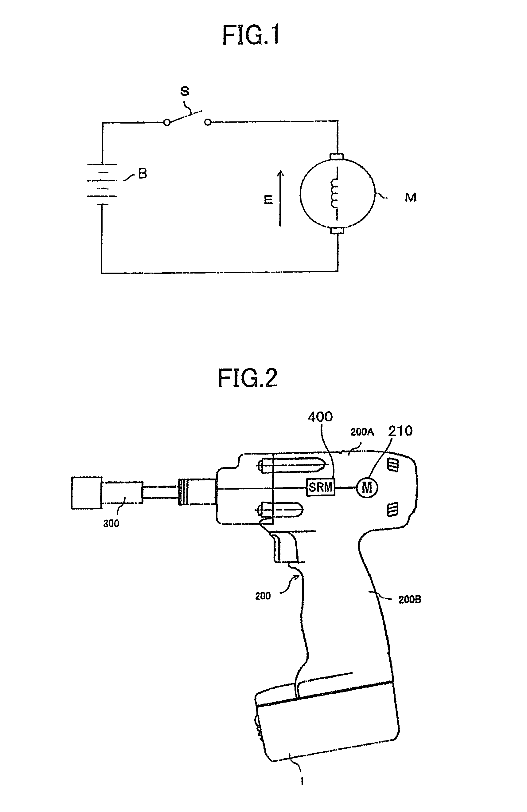
[0035]FIG. 2 shows a schematic view showing an illustrative example of a power tool. The power tool 200 shown therein is an electric screwdriver. Other power tools have a similar structure. The power tool 200 has a main body 200A, a handle 200B coupled to the main body 200A, and a battery pack 1 attached to the end portion of the handle 200B. The battery pack 1 houses a predetermined number of lithium battery cells connected in series.

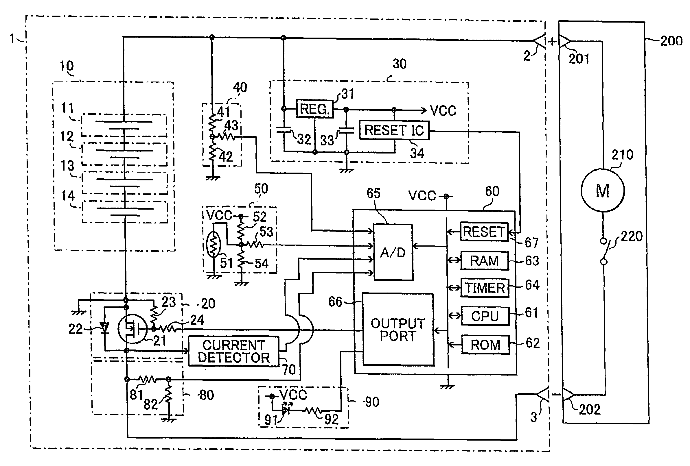
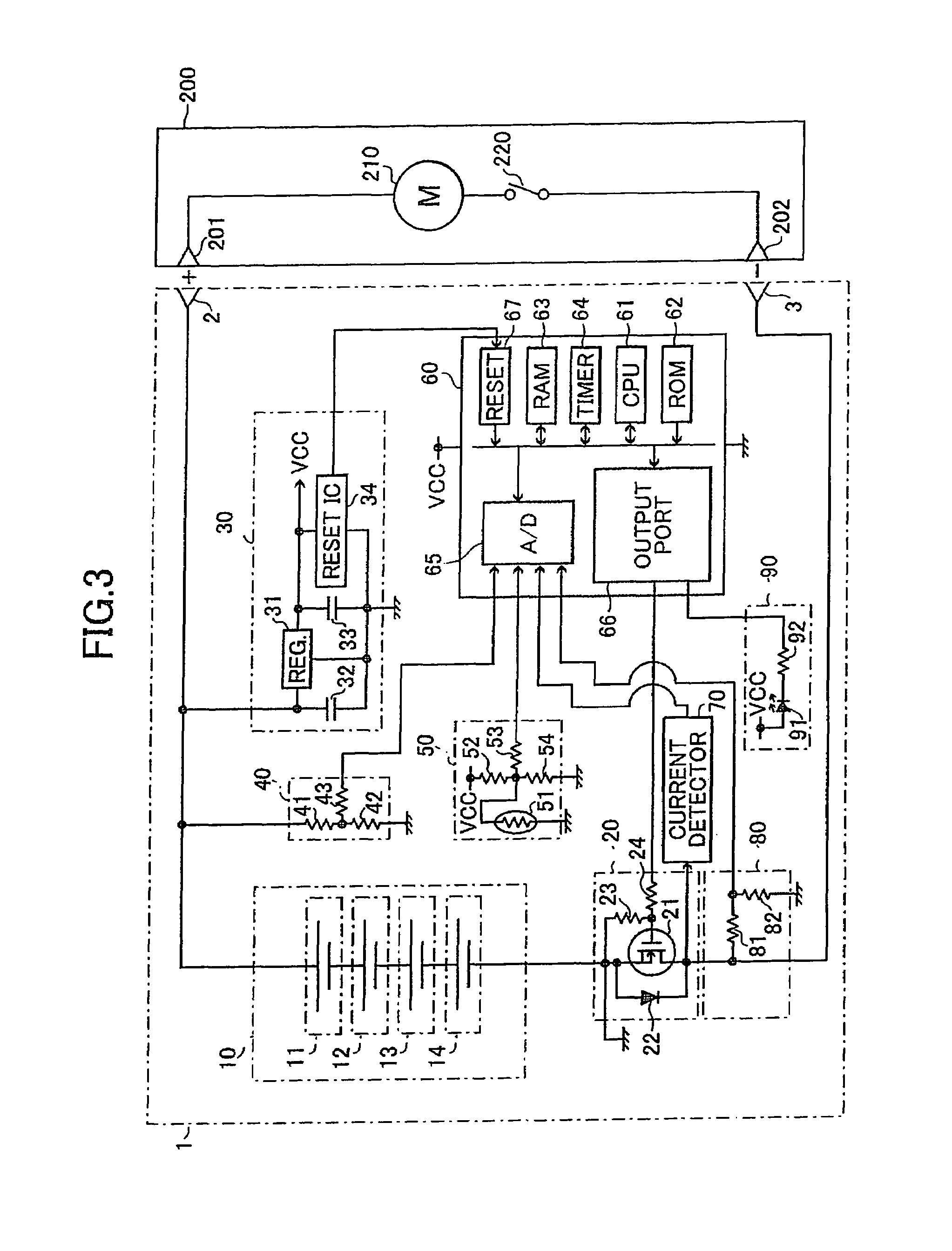
[0036]The main body 200A includes a motor 210, a speed reduction mechanism 400, and a screwdriver bit 300 attached to the distal end of the main body 200A. The motor 210 rotates when connected to the battery housed in the battery pack 1. The speed reduction mechanism 400 is operatively coupled to the motor 210, reduces the rotational speed of the motor 210, and transmits the reduced rotational speed to the screwdriver bi...


PUM

PropertyMeasurementUnit
voltageaaaaaaaaaa
voltageaaaaaaaaaa
voltageaaaaaaaaaa

Abstract

A cordless power tool uses a lithium battery as a power source of a motor and is provided with an overcurrent protection circuit. The circuit allows an overcurrent to instantaneously flow at the start-up time of the motor and shuts off an overcurrent which may flow when the motor is brought into a locked state during the use of the power tool.

Description

BACKGROUND OF THE INVENTION[0001]1. Field of the Invention[0002]The present invention relates to a cordless power tool using a lithium battery, and more particularly, to a cordless power tool having an overcurrent protection circuit to prevent an overcurrent from flowing in a lithium battery.[0003]2. Description of the Related Art[0004]In a power tool such as an electric screwdriver, an electric drill, an impact power tool, rotational power generated from an electric motor is applied to a speed reduction mechanism to reduce rotational speed and then transmitted to a bit attached to the distal end of the tool. Conventionally, the power tools are provided with a cord for connection to a commercial AC power source and the motor is rotated by the power supplied from the commercial AC power source. Recently, however, cordless power tools have been widely used, in which an alkaline secondary battery such as a nickel-cadmium battery or a nickel-hydrogen battery is used as a power source.[0...

Claims


Application Information

Patent Timeline
Patent Type & Authority Patents(United States)
IPC IPC(8): H01M10/46B25F5/00H01M50/204H01M50/247H01M50/296H02J7/00
CPCH01M2/1022H01M10/42H01M10/425Y02E60/10H01M50/204H01M50/247H01M50/296B25F5/00B23B45/02
Inventor FUNABASHI, KAZUHIKOARADACHI, TAKAOHANAWA, HIROYUKIOGURA, MASAYUKI
Owner KOKI HLDG CO LTD
Why Eureka
Try Eureka