Supercharge Your Innovation With Domain-Expert AI Agents!

Electronic equipment and digital camera

a technology of electronic equipment and digital cameras, applied in the field of electronic equipment, can solve the problems of high power consumption of hmi and visibility problem of the screen of an lcd, and achieve the effects of low power consumption, good operability, and good operability

Active Publication Date: 2009-04-21
ADVANCED INTERCONNECT SYST LTD
View PDF10 Cites 8 Cited by
  • Summary
  • Abstract
  • Description
  • Claims
  • Application Information

AI Technical Summary

Benefits of technology

"The present invention provides electronic equipment and a digital camera with a rotatable or pivotable controller that can display different functions based on its position in the axis direction. The controller can switch between a photograph mode, a setting mode, and a different setting mode to change processing conditions for an image. The camera can also have an indicator that displays the position of the controller on the screen and can switch between different functions based on the position of the controller. The invention improves the usability and low power consumption of the electronic equipment and the digital camera."

Problems solved by technology

However, there is a problem that power consumption is high in an HMI which uses an LCD.
In addition, a screen of an LCD has a visibility problem in bright outdoors.

Method used


Image

  • Electronic equipment and digital camera
  • Electronic equipment and digital camera
  • Electronic equipment and digital camera

Examples


first embodiment

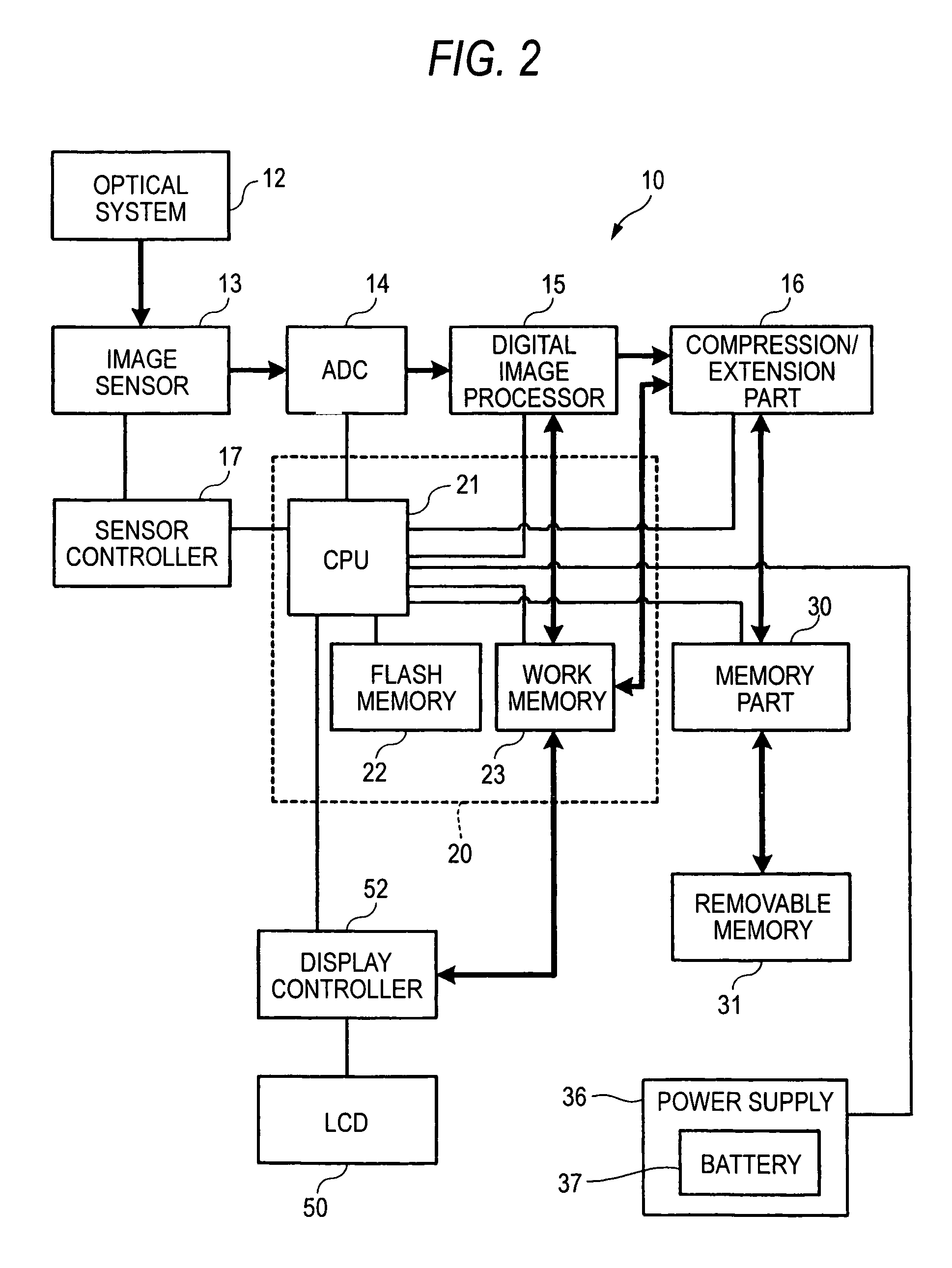
[0071]FIG. 2 is a block diagram showing a hardware configuration of a digital still camera (DSC) 10 as electronic equipment according to a first embodiment of the present invention.

[0072]An optical system 12 comprises a lens and an aperture, and an optical image of a subject is formed on a receiving surface of an image sensor 13.

[0073]The image sensor 13 is an area image sensor which comprises a pixel positioned discretely in two-dimensional space and a charge-transfer device such as a CCD (Charge Coupled Device). The image sensor 13 accumulates electric charge, which is obtained by photoelectric conversion of the optical image imaged by the optical system 12, in every pixel in a fixed time period, and outputs an electrical signal in response to a received amount of light in every pixel. The image sensor 13 can take color image information by providing a four-colored complementary color filter of C (Cyan), M (Magenta), Y (Yellow), and G (Green), or a primary color filter of R (Red),...

second embodiment

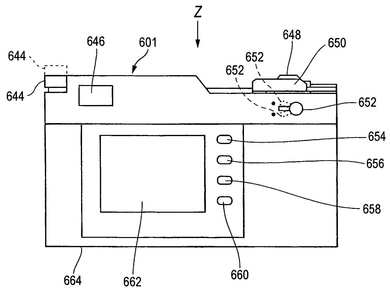
[0115]FIG. 15 is a block diagram showing a hardware configuration of a digital still camera (DSC) 601 as a digital camera according to a second embodiment of the present invention.

[0116]An optical system 610 comprises a plurality of lens 612 and an aperture 614. The optical system 610 forms an image of a subject on a receiving surface of an image sensor 620. Between the optical system 610 and the image sensor 620, a shutter screen 616 which is operated with the opening and shutting mechanism that is not illustrated is provided.

[0117]The image sensor 620 as a color image sensor mentioned in the Claims is an imaging element which comprises a photoelectric conversion element constituting a pixel positioned discretely in two-dimensional space and a charge-transfer device such as a CCD (Charge Coupled Device). The image sensor 620 is a so-called a CCD color image sensor or a CMOS color image sensor. The image sensor 620 is driven by a sensor controller which is not illustrated. The image...


PUM


Abstract

A digital camera having a color image sensor, an optical system, a rotatable first switch, and a second switch that switches between various modes. The second switch indicates an intermediate point corresponding to the photograph mode, a first point corresponding to the first setting mode, or a second point corresponding to the second setting mode. A first setting unit sets a first processing condition relating to a white balance of an image according to a rotation angle of the first switch in the first setting mode. A second setting unit sets a second processing condition relating to a data size of an image according to a rotation angle of the first switch in the second setting mode. Furthermore, a processing unit processes an output signal of the color image sensor according to a first processing condition and a second processing condition in the photograph mode.

Description

BACKGROUND OF THE INVENTION[0001]The present invention relates to electronic equipment such as digital camera, in particular, relates to HMI (Human Machine Interface) of electronic equipment.[0002]Generally, electronic equipment, in which an arbitrary function is selected from functions displayed on a screen by moving a cursor up, down, right, and left by operating a cross key, and a process according to the selected function is carried out, is known. (For example, refer to patent documents 1 and 2). A cross key is used in a multitude of electronic equipment because it can select a number of functions in one controller.[0003]On the other hand, a digital camera which uses a cross key and an LCD (liquid crystal display) as an HMI (Human Machine Interface) to set an image size, a white balance, an aperture, an exposure, an ISO film speed is known (for example, refer to patent document 3). In a menu operation with a cross key and an LCD, a number of items can be set with few switches by...

Claims


Application Information

Patent Timeline
Patent Type & Authority Patents(United States)
IPC IPC(8): H04N5/222H04N5/225H04N5/232
CPCH04N5/23293H04N23/50H04N23/631H04N23/633
Inventor SHIOHARA, RYUICHI
Owner ADVANCED INTERCONNECT SYST LTD
Features
  • R&D
  • Intellectual Property
  • Life Sciences
  • Materials
  • Tech Scout
  • Unparalleled Data Quality
  • Higher Quality Content
  • 60% Fewer Hallucinations
Learn More