System and method for image composition using position sensors

a position sensor and image composition technology, applied in the field of compound xray imaging, can solve the problems of only practical re-registration, significant negative effect of the resultant image, and large distortion of the image intensifier system, and achieve the effect of facilitating digital subtraction angiography

Inactive Publication Date: 2009-04-21
GENERAL ELECTRIC CO
View PDF5 Cites 88 Cited by
  • Summary
  • Abstract
  • Description
  • Claims
  • Application Information

AI Technical Summary

Benefits of technology

[0022]In an embodiment, the image processor facilitates digital subtraction angiography using the image data and the positional data. In an embodiment, the image processor provides feedback for positioning an image acquisition device based on the positional data and the image data. In an embodiment, the image processor is configured to obtain spatial measurements in the composed image based on the image data and the positional data.

Problems solved by technology

Historically, image intensifier systems produce much distortion.
One of the challenges with DSA is to maintain registration between the subtraction pair of images.
Even small mis-registration due to patient respiration, or c-arm mechanical instability can have a significant negative effect on the resultant image.
Although some systems have software features that allow automatic, or manual mask re-registration, re-registration is only practical when solving for small misalignments.
This lack of movement constrains a region where DSA may be used or requires acquiring new masks each time the imaging system is moved with respect to the patient.
Although mobile C-arms are becoming more sophisticated in order to meet the needs of new and emerging intervention methods, there are some performance limitations that are constrained by the need to maintain mobility.
Compared to a fixed-room system, one such constraint is an inability to link the C-arm and operating table positions and geometries as a single mechanical gantry system.

Method used


Image

  • System and method for image composition using position sensors
  • System and method for image composition using position sensors
  • System and method for image composition using position sensors

Examples


Embodiment Construction

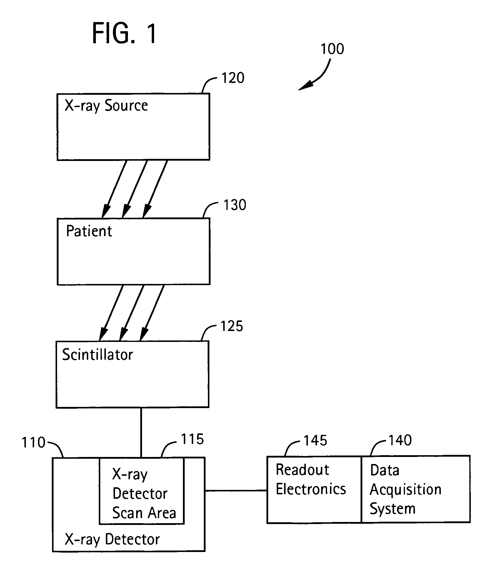
[0034]FIG. 1 illustrates an imaging system 100 used in accordance with an embodiment of the present invention. The imaging system 100 includes a plurality of subsystems. For the purposes of illustration, the imaging system 100 is described as an x-ray system. The imaging system 100 includes subsystems, such as an x-ray detector 110 including an array 115 of detector cells, an x-ray source 120, a scintillator 125, and an object 130. The imaging system 100 also includes a data acquisition system 140 with read out electronics 145. In an embodiment, the scintillator 125 comprises a screen positioned in front of the detector 110. In an embodiment, the detector 110 is an amorphous silicon flat panel detector. The object 130 may be a patient or another object to be imaged.

[0035]The object 130 is positioned in imaging system 100 for imaging. In one exemplary system, an x-ray source 120 is positioned above the object 130. The x-ray detector 110 is positioned below the object 130. The scintil...


PUM

PropertyMeasurementUnit
image compositionaaaaaaaaaa
areaaaaaaaaaaa
fluoroscopic imagingaaaaaaaaaa

Abstract

Certain embodiments of the present invention provide systems and methods for image composition. Certain embodiments include acquiring a first image of an object using an imager, obtaining first positional information for the imager with respect to the object, acquiring a second image of the object using the imager, obtaining second positional information for the imager with respect to the object, and creating a composed image using the first and second images. A spatial relationship between the images is maintained using the positional information. A composed image may be created by constructing a memory map of image data related to the object and inserting the images into the memory map based on the positional information, for example. A composed image may be created by combining the images based on the positional information, for example.

Description

RELATED APPLICATIONS[0001][Not Applicable]FEDERALLY SPONSORED RESEARCH OR DEVELOPMENT[0002][Not Applicable]MICROFICHE / COPYRIGHT REFERENCE[0003][Not Applicable]BACKGROUND OF THE INVENTION[0004]The present invention generally relates to x-ray imaging. In particular, the present invention relates to a system and method for compound x-ray imaging using position sensors.[0005]Digital imaging systems may be used to capture images to assist a doctor in making an accurate diagnosis. Digital radiography and / or fluoroscopy imaging systems typically include a source and a detector. Energy, such as x-rays, produced by the source travel through an object to be imaged and are detected by the detector. An associated control system obtains image data from the detector and prepares a corresponding diagnostic image on a display.[0006]The detector may be a flat panel detector, such as an amorphous silicon flat panel detector, for example. Alternatively, the detector may be an image intensifier or othe...

Claims


Application Information

Patent Timeline
Patent Type & Authority Patents(United States)
IPC IPC(8): G01N23/04G06V10/24
CPCA61B6/481A61B6/504A61B6/5241G06K9/32G06T5/50G06T7/0024G06K2009/2045G06T2200/32G06T2207/10121G06T2207/30004G06T7/30G06V10/16G06V10/24H04N1/387
Inventor JENSEN, VERNON THOMASLEPARMENTIER, RICHARDBATTLE, VIANNEY PIERRE
Owner GENERAL ELECTRIC CO
Why Eureka
Try Eureka