Controlled phase transition of metals

a phase transition and metal technology, applied in the field of physical chemistry, can solve the problems of wasting 90% of energy input as heat, unable to harness electromagnetic energy for controlling liquid/solid phase transition, and unable to achieve the effect of transforming metals quickly and reducing energy consumption

Inactive Publication Date: 2009-04-28
ELEMETRIC
View PDF22 Cites 3 Cited by
  • Summary
  • Abstract
  • Description
  • Claims
  • Application Information

AI Technical Summary

Benefits of technology

[0013]Use of a coherent disruptive electromagnetic field makes it possible to direct the energy necessary to disrupt molecular bonding. The disclosed method tunes coherent electromagnetic fields to initiate phase transitions by targeting bond energies so precisely that little heat is generated. By tuning input energy to one or more bond energies of a metal, phase transitions can be accomplished with far less energy lost as heat than is typically the case when solid metals undergo a phase change.

Problems solved by technology

Flat measuring devices, for example, are used to measure nuances in the earth's magnetic field; however, such devices only give a single orientation to either north or south poles or provide only the general strength of the EM field.
Energy expenditure with either process is considerable, with over 90% of energy input being wasted as heat.
Despite progress in developing energy efficient methods, particularly in metal processing, current technologies have yet to harness electromagnetic energy for controlling liquid / solid phase transitions.

Method used


Image

  • Controlled phase transition of metals
  • Controlled phase transition of metals
  • Controlled phase transition of metals

Examples


example 1

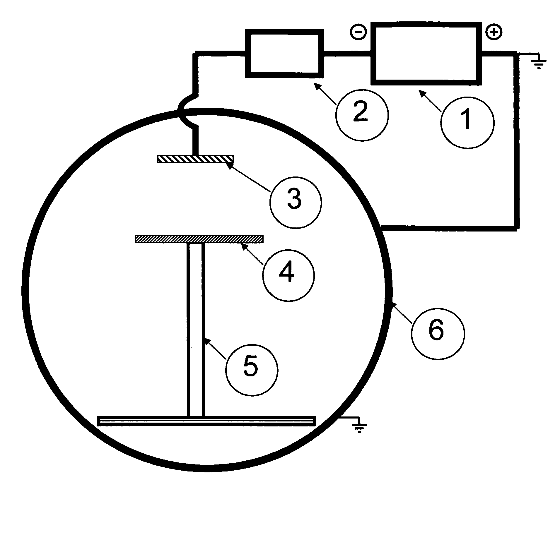
Apparatus for Generating Electromagnetic Field

[0031]A vacuum chamber was constructed of ⅜″ thick A6 steel with a diameter of 30 in and a length of 36 in. The chamber was pumped with a VHS 6 oil diffusion pump with 400 ml of DuPont 704 diffusion pump oil. The pump was backed by a 30 CFM Pfeiffer mechanical pump with 1 liter of Stokes C-77 pump oil. The chamber was rough pumped by a Leybold E-75 pump with a WU 500 blower package with Fomblin oil. The pump down of the chamber was controlled by internally designed circuits utilizing an MKS 636 baratron and a BP ion gauge. The apparatus includes a 6×1×20 in, 99.99% pure nickel target with water cooling and two power inputs. This cathode was driven by a Miller 304 CC / CV power supply and a Miller analog pulsing unit.

[0032]An alternative to the 6×20 in target cathode are small round target cathodes with a surface diameter of 1 to 6 in. This target configuration can assist in the localization of the transfer of current from the cathode to th...

example 2

Electromagnetic Field Induced Phase Transition of Aluminum

[0033]Aluminum was selected as the substrate. The pulse current generated by the electromagnetic field using the apparatus described in Example 1 was 300 Hz. Localization of the current outflow from the cathode to the anode in the pulsed mode must be locally confined. At the reported powers, the area of electron flow was confined consistently to an area approximately 3 inches in diameter. This confinement allows creation of a coherent beam in which the EM field travels.

[0034]An 8×¼×12 in 6061T6 aluminum plate was placed in an aluminum 2×2×¼ in wall thickness square channel of conductive aluminum that was 22 in tall. This placed the substrate 8 in from the surface of the target. The apparatus was constructed as described in Example 1 and the chamber was pumped to a level of 5E-4 Torr. The power supply was set to 300 amps, 20 V output. The pulsing unit was set with at background current of 75 amps, a pulse width of 2 ms, and a ...

example 3

Electromagnetic Field Induced Phase Transition of Steel

[0039]A steel plate was placed 3 feet from the target and exposed to a coherently focused electromagnetic beam for 10 s to 2 min using the apparatus described in Example 1 under the conditions set forth in Example 2. The metal began to flow at 200° C., which is significantly lower than heat-induced melting, which requires a temperature of 1515° C.


PUM

PropertyMeasurementUnit
frequencyaaaaaaaaaa
temperaturesaaaaaaaaaa
diameteraaaaaaaaaa

Abstract

A process for electromagnetic (EM) energy-induced solid to liquid phase transitions in metals is disclosed. The method utilizes coherent EM fields to transform solid materials such as silicon and aluminum without significant detectable heat generation. The transformed material reverts to a solid form after the EM field is removed within a period of time dependent on the material and the irradiation conditions.

Description

BACKGROUND OF THE INVENTION[0001]1. Field of the Invention[0002]The invention relates generally to the field of physical chemistry and particularly to the use of electromagnetic fields to control solid / liquid phase transitions in metals.[0003]2. Description of Background Art[0004]Electromagnetic (EM) fields are used in several practical applications, including motors and radio wave transmissions. An EM field is considered to be a unique force different from the forces organizing gravity, particle mass and elemental charge. The relation of electromagnetism in terms of structure to rest mass and inertial mass has yet to be fully understood, perhaps explaining why electromagnetic applications are fairly limited and have not been applied to the development of new mechanical and medical uses.[0005]A major shortcoming of conventional descriptions of EM fields is the tendency to look at field generation as 2-dimensional around current flowing around a wire. Current theory views EM fields a...

Claims


Application Information

Patent Timeline
Patent Type & Authority Patents(United States)
IPC IPC(8): C21D10/00
CPCB22D27/02C21D1/04C21D10/00C22F3/02
Inventor MCGRATH, TERRENCE S.
Owner ELEMETRIC
Why Eureka
Try Eureka