

Substrate processing method using alkaline solution and acid solution
a substrate and acid solution technology, applied in the direction of cleaning process and apparatus, chemistry apparatus and processes, liquid cleaning, etc., can solve the problems of etching thickness reaching 2.0 nm and disadvantageous increase of substrate etching quantity, so as to reduce the processing time of substrate and suppress the quantity of etching
- Summary
- Abstract
- Description
- Claims
- Application Information
AI Technical Summary
Benefits of technology
Problems solved by technology
Method used
Image

Examples
first embodiment
[0050]
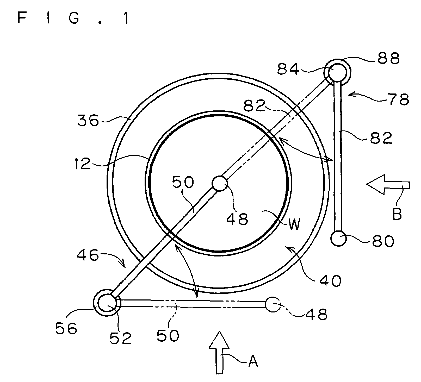
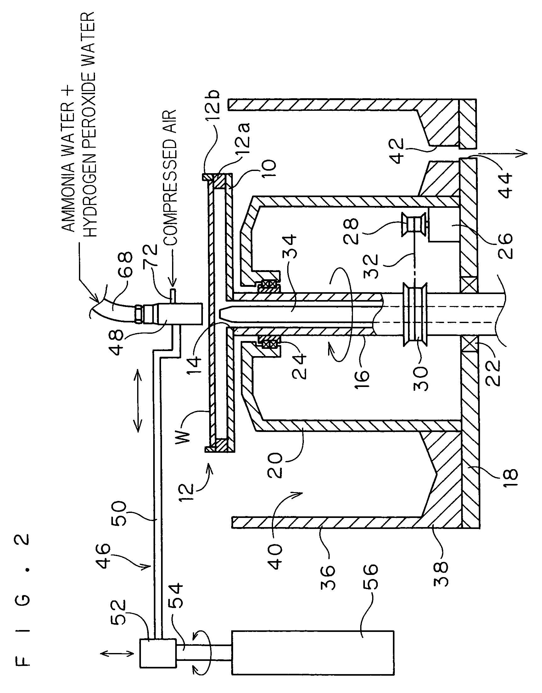
[0051]FIGS. 1 to 3 illustrate an exemplary structure of a substrate processing apparatus according to a first embodiment of the present invention. FIG. 1 is a plan view of the apparatus. FIG. 2 is a schematic block diagram showing a principal part of the apparatus as viewed along arrow A in FIG. 1 in an end surface. FIG. 3 is a schematic block diagram showing the principal part of the apparatus along arrow B in FIG. 1 in another end surface. FIG. 2 omits illustration of a supply mechanism for an etchant, while FIG. 3 omits illustration of supply mechanisms for ammonia water and hydrogen peroxide water.
[0052]This substrate processing apparatus comprises a discoidal spin base 10 horizontally supporting a substrate W such as a semiconductor wafer. A plurality of, e.g., six chuck pins 12 for grasping the peripheral edge of the substrate W are circumferentially arranged on the upper peripheral edge of the spin base 10 at regular intervals. Each of the chuck pins 12 comprises a supp...
second embodiment
[0090]
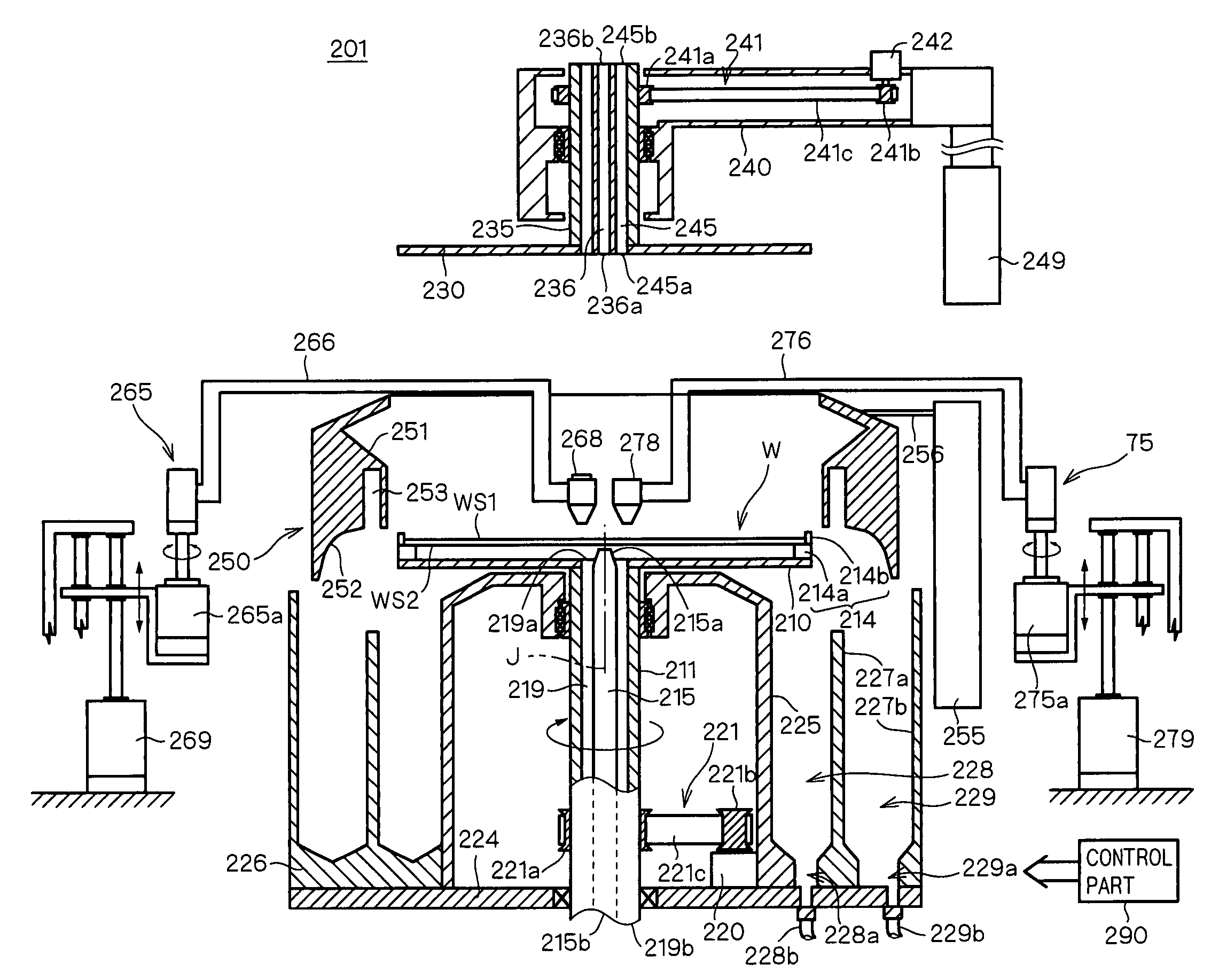
[0091]A second embodiment of the present invention is now described with reference to FIGS. 10 to 22. FIG. 10 is a longitudinal sectional view showing the structure of a substrate processing apparatus 201 according to this embodiment. This substrate processing apparatus 201 is a single-substrate type apparatus cleaning a substrate W which is a semiconductor wafer (more specifically, a silicon wafer). The substrate processing apparatus 201 mainly comprises a spin base 210 holding and rotating the substrate W, an alkaline solution nozzle 268 supplying an alkaline solution imparted with megasonic vibrations to the substrate W held on the spin base 210, an acid solution nozzle 278 supplying an acid solution to the substrate W held on the spin base 210, a deionized water nozzle 236 supplying deionized water to the substrate W held on the spin base 210, a receiving member 226 constituting a discharge tank or the like disposing or recovering used processing solutions (the alkaline so...
third embodiment
[0173]
[0174]A third embodiment of the present invention is now described with reference to FIGS. 23 to 29.
[0175]FIGS. 23 to 25 show an exemplary structure of a substrate processing apparatus according to this embodiment. FIG. 23 is a plan view of the apparatus. FIG. 24 is a schematic block diagram showing a principal part of the apparatus as viewed along arrow A in FIG. 23 in an end surface. FIG. 25 is a schematic block diagram showing the principal part of the apparatus as viewed along arrow B in FIG. 23 in another end surface. FIG. 24 omits illustration of an acid solution supply mechanism, while FIG. 25 omits illustration of an alkaline solution supply mechanism.
[0176]This substrate processing apparatus comprises a discoidal spin base 310 horizontally supporting a substrate W such as a semiconductor wafer. A plurality of, e.g., six chuck pins 312 for grasping the peripheral edge of the substrate W are circumferentially arranged on the upper peripheral edge of the spin base 310 at...
PUM
 Abstract
Description
Claims
Application Information