Heat exchanger for high purity and corrosive fluids

a heat exchanger and high purity technology, applied in the direction of indirect heat exchangers, domestic cooling devices, lighting and heating apparatus, etc., can solve the problems of large amount of heat required to raise and maintain the temperature of the etching/cleaning fluid, chemically attacked when exposed to the corrosive fluid, and common materials traditionally utilized in the fabrication of heat exchangers such as metals are not chemically compatible, etc., to achieve easy and inexpensive manufacturing, rugged and reliable operation, and compact and efficien

Inactive Publication Date: 2009-05-05
APPLIED INTEGRATED SYST
View PDF7 Cites 3 Cited by
  • Summary
  • Abstract
  • Description
  • Claims
  • Application Information

AI Technical Summary

Benefits of technology

[0012]It is another object of the present invention to provide a heat exchanger which is appropriate for use with fluids wherein purity and cleanliness are essential.
[0013]It is yet another object of the present invention to provide a heat exchanger which is compact and efficient.
[0014]It is still another object of the present invention to provide a heat exchanger which is rugged and reliable in operation.
[0015]It is yet another object of the present invention to provide a heat exchanger which is easy and inexpensive to manufacture.
[0016]The present invention allows for the heating of high-purity and / or corrosive fluids by utilizing a cylindrical shaped conductive material with integral spiral shaped channels wherein inert tubing is wrapped. The unit is compact, highly expandable, and inexpensive to produce. This invention can also be used for both heating and cooling and is not limited to high-purity and / or chemically aggressive fluids.

Problems solved by technology

Because both the process temperatures and the heat capacities of the etching / cleaning fluids are relatively high, a rather large amount of heat is required to raise and maintain the temperature of the etching / cleaning fluid.
Due to the corrosive nature of the typical etching / cleaning fluids used in the semiconductor industry, common materials traditionally utilized in the fabrication of heat exchangers such as metals are not chemically compatible, and therefore, are unacceptable.
While metals are extremely good thermal conductors, they are chemically attacked when exposed to these corrosive fluids.
As a result, the fluid becomes contaminated and can no longer be used as an etching / cleaning agent.
Although chemically inert, Teflon™ is a very poor conductor, and therefore, the thermal transfer between the heat source and the fluid is limited.
These coils result in “dead” zones where particles reside and shed over time.
This makes the described arrangement less desirable for high purity applications.
This is unacceptable because, due to stringent process requirements, etching / cleaning fluids must be free of foreign particles in order to avoid the contamination and destruction of microcircuits formed in the silicon wafers.
Another problem associated with immersion type heaters is related to the geometry of such coils.
High temperature gradients can often times degrade the chemical (e.g., lead to premature chemical aging).
The combination of hot spots and the micro-bubbles greatly reduce both the efficiency of the heat exchanger and the heating element life, and can also lead to chemical degradation.
Another common problem associated with immersion type heat exchangers is that the thin layer of Teflon™ burns immediately when the heating elements become exposed to air.
This is a common mode of failure that significantly increases maintenance and parts replacement costs.
Although thermoelectric modules are useful devices that can cool and heat the conductive material, they are limited to low wattage applications.
Hence, this heat exchanger device would not be suitable for heating the common semiconductor etching and cleaning fluids.
Another problem associated with the design described in the prior art listed above, is that it is very difficult to form tight bends in known inert tubing materials.
This creates several problems when designing and manufacturing heat exchangers, wherein tubing typically includes multiple bends.
First, known inert tubing is easily kinked, and cannot therefore be bent into small diameter bends.
Rather, such tubing requires a large bend radius and is, therefore, often bent outside of the heat exchanger, thereby reducing the heating efficiency of the heat exchanger and increasing its size.
In either situation, because of the large bend radii of the plastic tubing, less tubing can be used per unit surface area of the heat exchanger, thereby reducing the thermal efficiency of the heat exchanger and dramatically increasing its size.
While the turbulence caused by the inserts facilitates increased thermal transfer between the heat exchanger and the fluid, the inserts also cause dead zones within the fluid flow, increasing the potential for particle build-up and contamination of the etching / cleaning fluid.
While reducing the tubing wall thickness enhances the heat transfer between the conductive plate and fluid, it dramatically reduces the pressure rating of the inert tubing and dramatically increases its bend radius.
This severely limits the temperature and pressure ranges within which the heat exchanger can operate, making such solutions unsuitable for many heating applications.

Method used


Image

  • Heat exchanger for high purity and corrosive fluids
  • Heat exchanger for high purity and corrosive fluids
  • Heat exchanger for high purity and corrosive fluids

Examples


Embodiment Construction

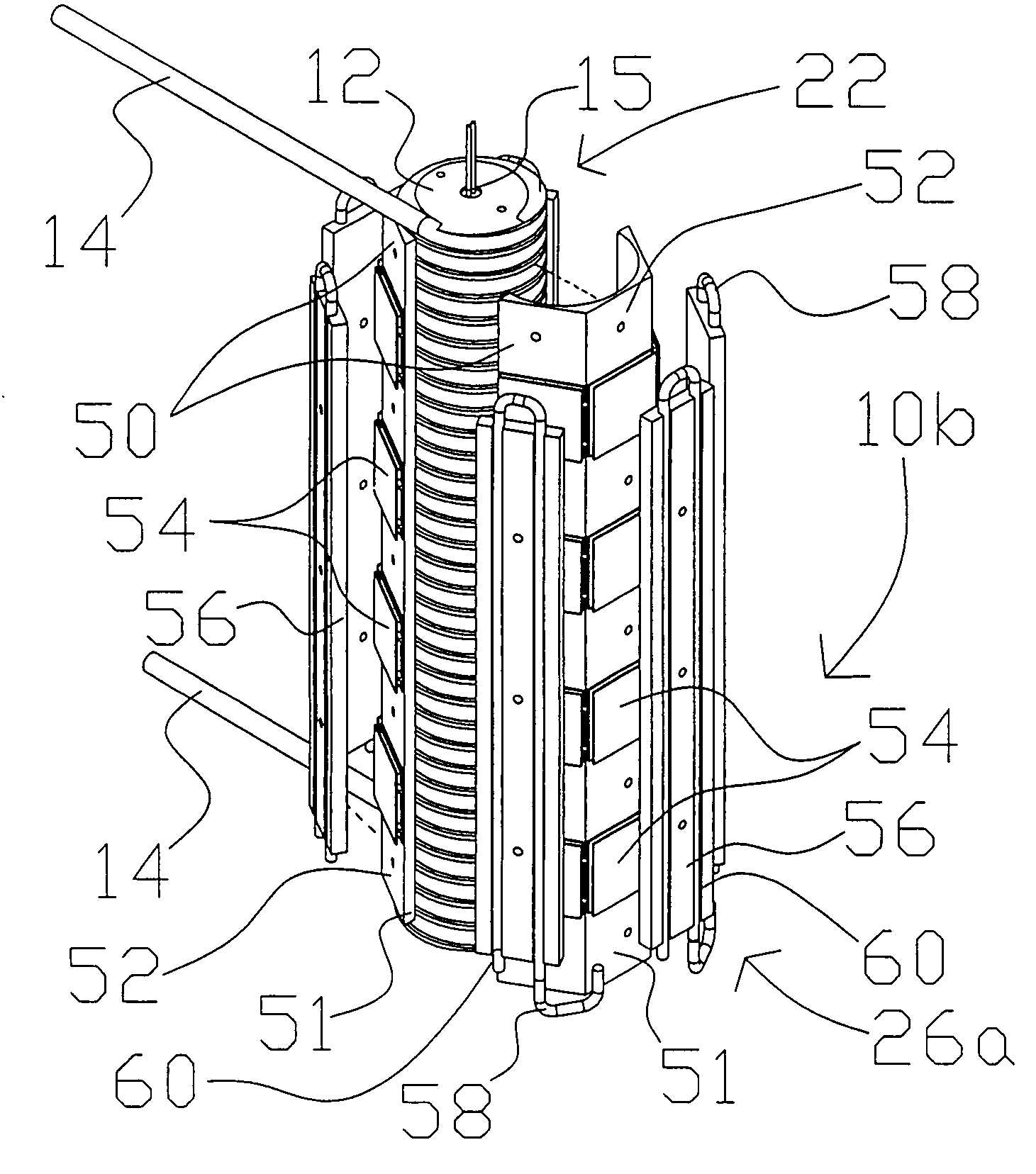
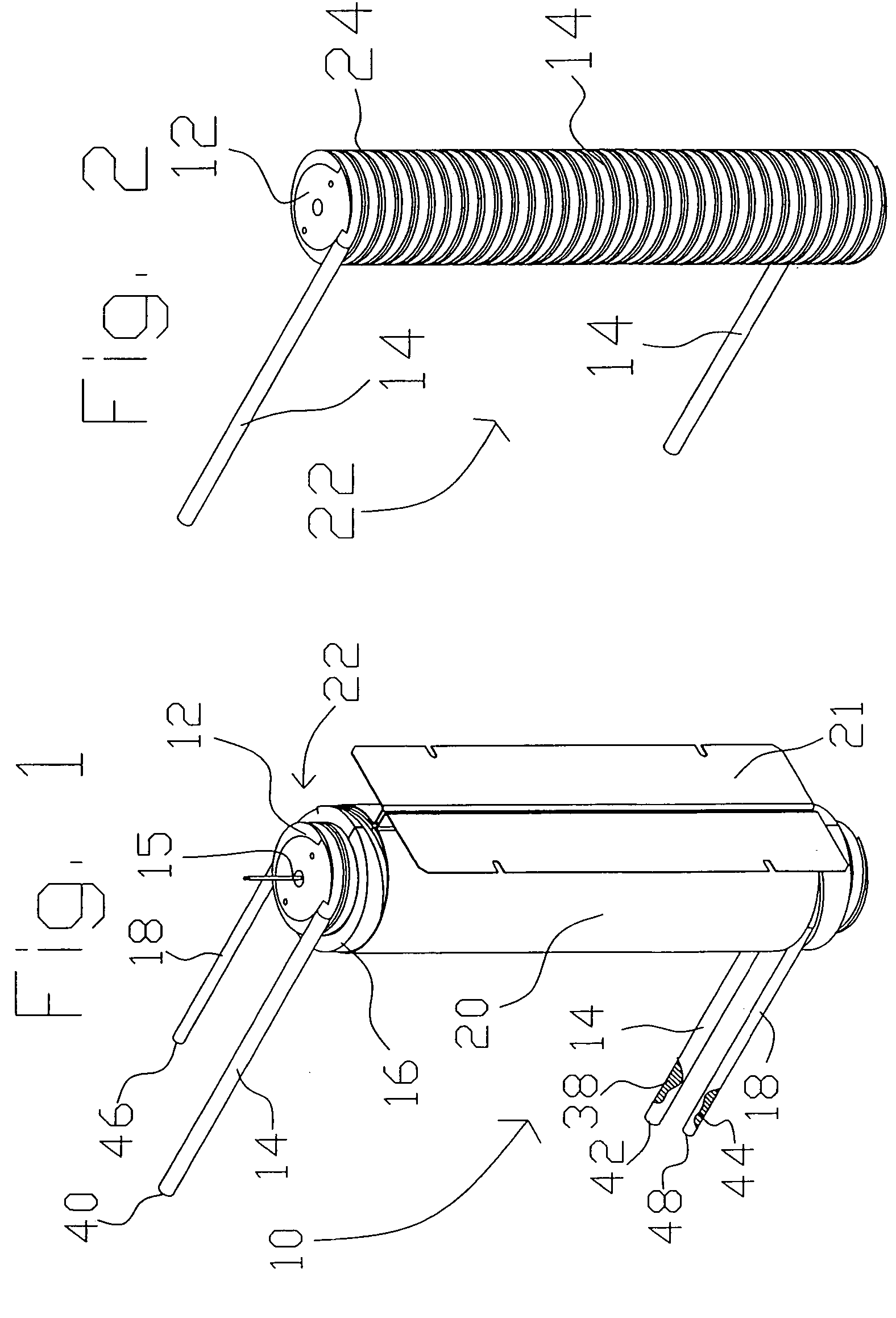
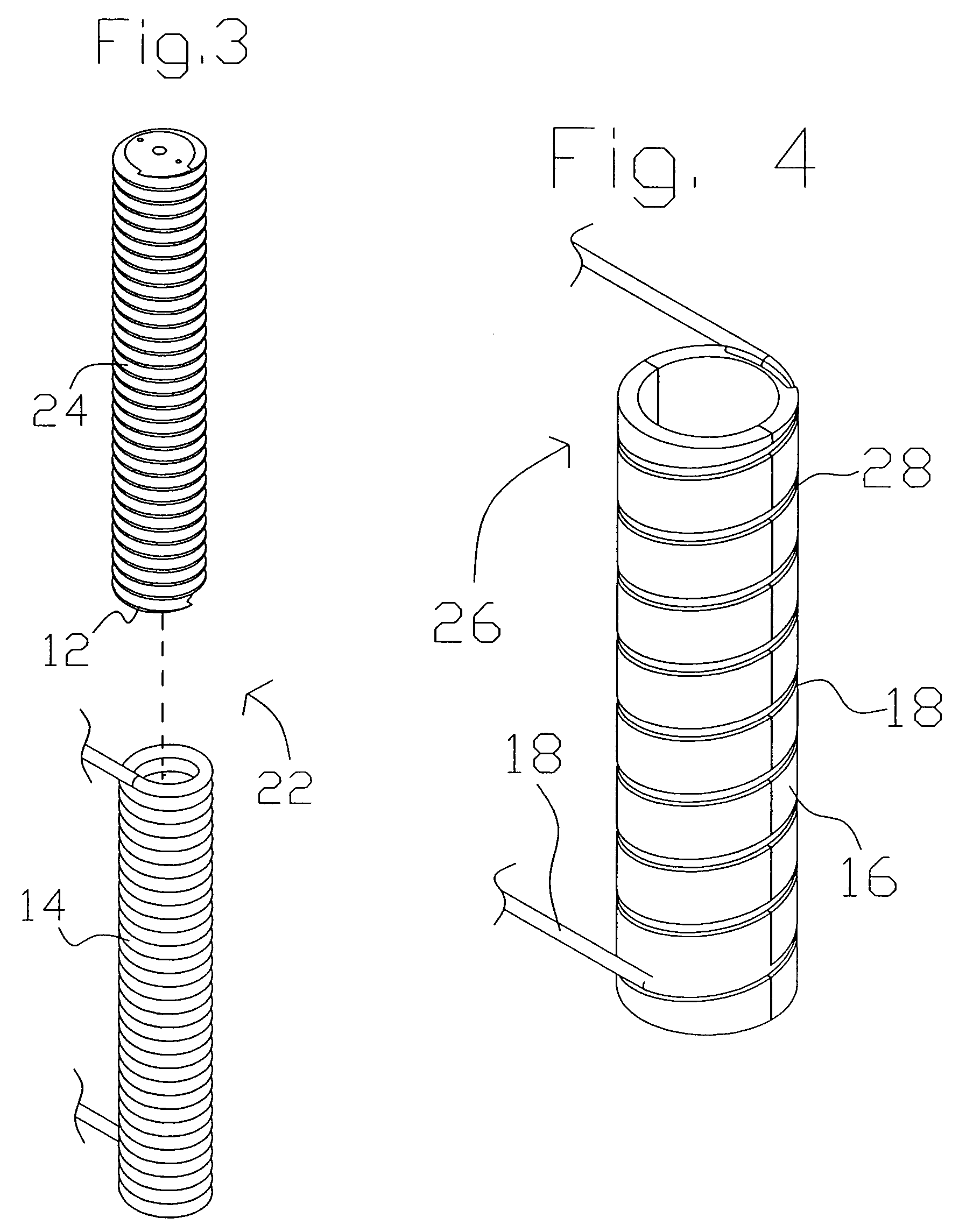
[0038]This invention is described in the following description with reference to the Figures, in which like numbers represent the same or similar elements. While this invention is described in terms of modes for achieving this invention's objectives, it will be appreciated by those skilled in the art that variations may be accomplished in view of these teachings without deviating from the spirit or scope of the present invention. The embodiments and variations of the invention described herein, and / or shown in the drawings, are presented by way of example only and are not limiting as to the scope of the invention. Unless otherwise specifically stated, individual aspects and components of the invention may be omitted or modified, or may have substituted therefore known equivalents, or as yet unknown substitutes such as may be developed in the future or such as may be found to be acceptable substitutes in the future. The invention may also be modified for a variety of applications whi...


PUM


Abstract

A heat exchange apparatus (10, 10, 10b) for selectively heating and/or cooling a process fluid (38). A process fluid tubing 14 is wrapped around a primary thermally conductive cylinder (12) having a spiral groove (24) therein adapted for closely accepting the process fluid tubing (14) and increasing the area in thermal contact therebetween. The process fluid tubing (14) is a generally chemically inert tubing. The spiral groove (24) supports the process fluid tubing (14) such that the process fluid tubing (14) can be bent in a radius smaller than the natural minimum bend radius of the process fluid tubing (14). Various embodiments have a cooling apparatus (26, 26a) for cooling the process fluid (38). The cooling apparatus (26, 26a) has a outer thermally conductive cylinder (16) or an outer thermal reservoir (50) cooled alternatively by coolant fluid (44) passing through cooling fluid tubing (18), by a plurality of thermoelectric modules (54), or by a combination thereof.

Description

RELATED APPLICATIONS[0001]The present application is a divisional of U.S. patent application Ser. No. 10 / 365,020, filed Feb. 12, 2003 now U.S. Pat. No. 6,804,965 by the same inventor, which is incorporated herein by reference in its entirety.TECHNICAL FIELD[0002]The present invention relates generally to a heat exchanger device, and more particularly to a novel compact heat exchanger design configuration using polymeric tubing. The predominant current application for the inventive heat exchanger apparatus is for the temperature control of high purity and / or corrosive fluids.BACKGROUND ART[0003]Many industries require the use of heat exchangers to regulate the temperature of high purity and / or corrosive fluids. For example, microchip fabrication within the semiconductor industry requires heating and temperature regulation of the etching and / or cleaning fluids used to etch and / or clean silicon wafers and microcircuit lines. Because both the process temperatures and the heat capacities...

Claims


Application Information

Patent Timeline
Patent Type & Authority Patents(United States)
IPC IPC(8): F25B21/02F25D11/00F28D7/02F25D31/00
CPCF25B21/02F28D7/022F25B2321/025F25D31/002
Inventor ABRAS, ALEXEI D.
Owner APPLIED INTEGRATED SYST
Why Eureka
Try Eureka