Headphone receiver apparatus for use with low power transmitters

a receiver and headphone technology, applied in the field of radio transmitters and receivers, can solve the problems of unsatisfactory performance of known fm receiver headphones when used with low-power fm transmitter products, component cost of achieving increased sensitivity, and poor sensitivity, so as to reduce the loading of other conductors and improve low-noise performance.

Inactive Publication Date: 2009-05-12
AERIELLE TECH
View PDF9 Cites 10 Cited by
  • Summary
  • Abstract
  • Description
  • Claims
  • Application Information

AI Technical Summary

Benefits of technology

[0008]The headphone receiver apparatus for use with low power transmitters of this invention provides an improved headphone apparatus having a pair of headphone speaker enclosures connected by a generally arcuate headband, with the receiver electronics contained in one of the enclosures. An antenna element in the form of a spring steel band or a plastic cable / antenna band where one of the conductors is utilized as the antenna is configured generally concentric with but radially offset from the headband and the user's head by at least 0.5 inches over at least some length of the antenna. Low-noise performance is improved by incorporation of a low noise amplifier before the receiver IC, and a lumped-element bandpass filter (or, alternatively, a varactor-tuned bandpass filter) interposed between the low noise amplifier and the receiver IC. A base-loading inductor may be used to tune the antenna element to resonance, with or without capacative end-loading. An isolator in the form of lumped inductors, ferrite beads, or a parallel resonant LC circuit may be used to isolate the shield conductor at RF frequencies, and / or to reduce the loading of the other conductors.

Problems solved by technology

Known FM receiver headphones have unsatisfactory performance when used with low power FM transmitter products.
In such an environment a proper receiver may be designed with good selectivity (i.e., the ability to reject unwanted adjacent channel signals) but not very good sensitivity due to the intermodulation problems it can cause, and the component cost of achieving increased sensitivity.

Method used


Image

  • Headphone receiver apparatus for use with low power transmitters
  • Headphone receiver apparatus for use with low power transmitters
  • Headphone receiver apparatus for use with low power transmitters

Examples


first embodiment

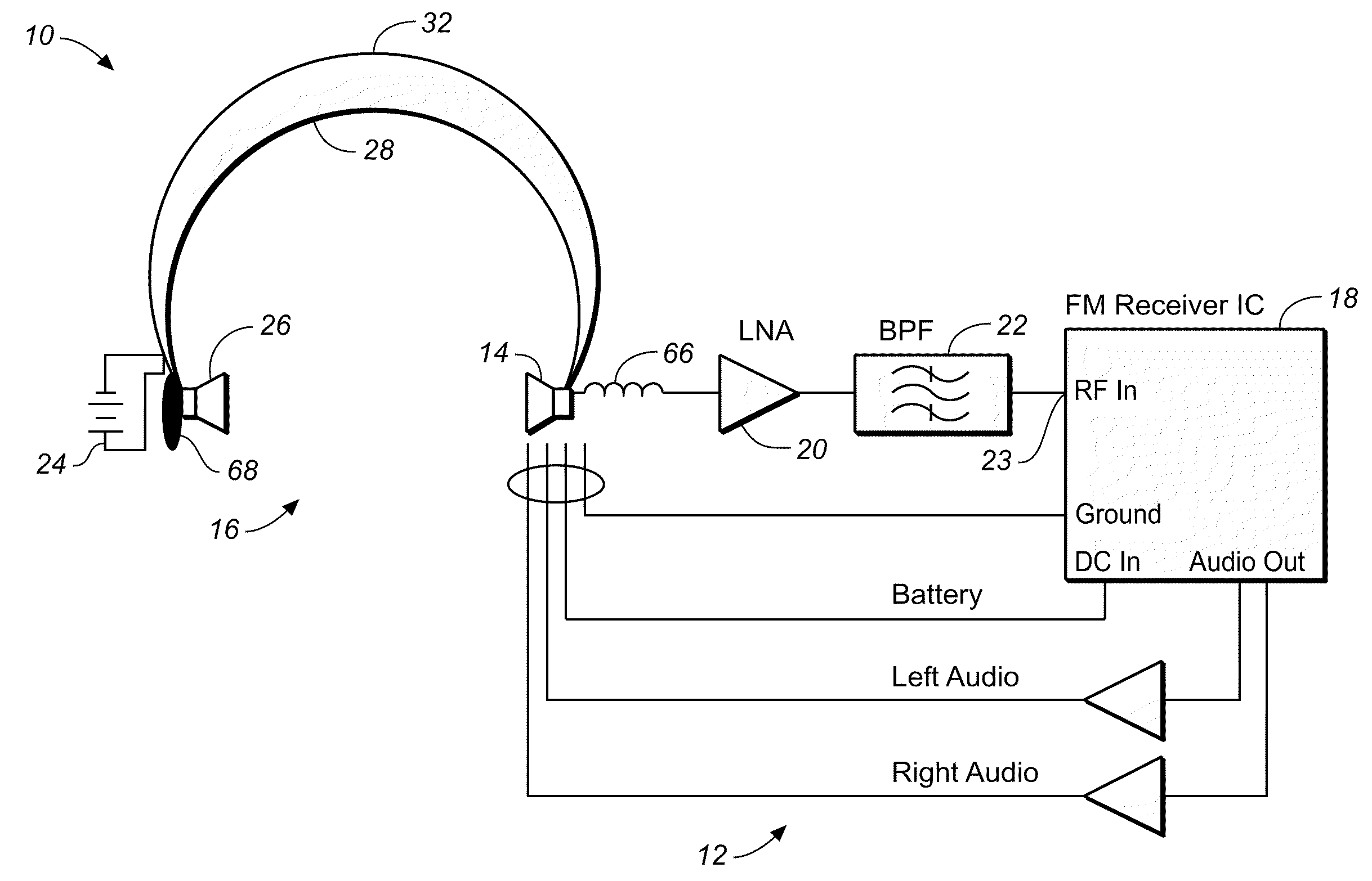
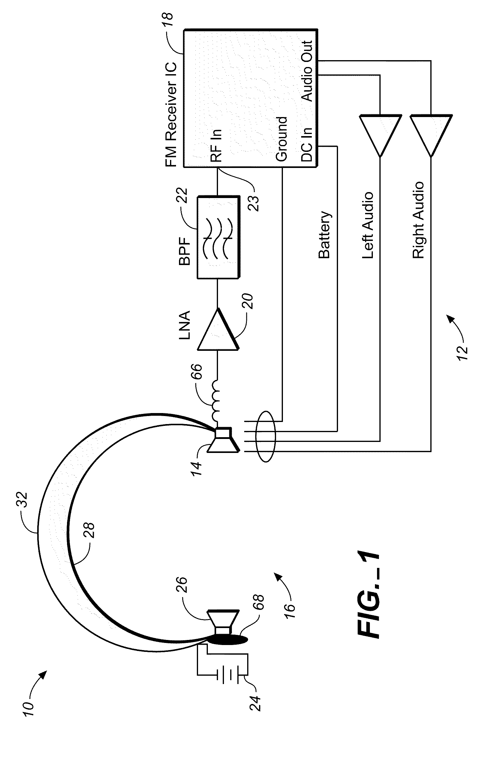
[0020]Referring to FIGS. 1 and 2, wherein like reference numerals refer to like components in the various views, FIG. 1 is a schematic view of a headphone receiver apparatus 10 of this invention. Headphone receiver apparatus 10 includes receiver electronics 12 incorporated into a first speaker enclosure or side 14 of headset 16, beginning with a conventional FM receiver IC (integrated circuit) 18 and enhancing performance by connecting a low-noise amplifier 20 and band pass filter 22 to RF In 23. The low-noise amplifier 20 reduces the noise figure of the receiver IC 18 from 9-10 dB (for the IC alone) to about 3 dB. The band pass filter 22, with a bandwidth of about 2 MHz, reduces the number of high-power commercial FM stations the receiver chip 18 sees, thereby improving intermodulation performance. In this embodiment, band pass filter 22 is a fixed tuning lumped element filter tuned to only the portion of the band being used (typically 88.1 MHz to 88.9 MHz). Battery compartment 24 ...

embodiment 50

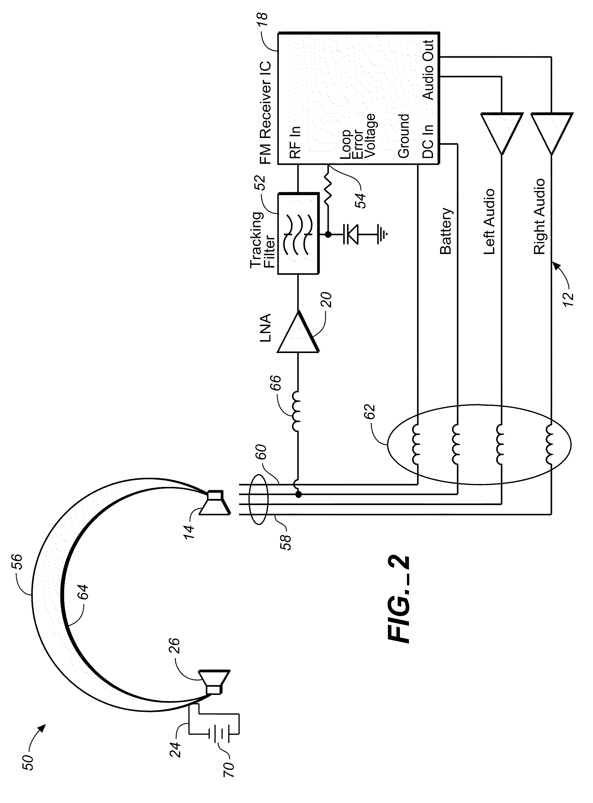
[0022]FIG. 2 is a schematic view of an alternate embodiment 50 of a headphone receiver apparatus of this invention. This embodiment 50 uses a varactor-tuned tracking filter 52 interposed between low noise amplifier 20 and receiver IC 18, which is capable of being tuned over the entire FM band (i.e., 88 to 108 MHz). Tuning of this filter 52 is derived from the loop error voltage 54 in the receiver's local oscillator phase locked loop.

[0023]This alternate embodiment 50 uses a hard plastic cable / antenna band 56 with a narrow channel along one edge to route a multi-conductor cable 58. One conductor such as the battery return lead (ground) 60 is utilized as the antenna element. This is accomplished by isolating this conductor from ground on the receiver 18 PCB with an isolator 62 such as a series inductor, ferrite bead, or parallel resonant tank circuit. This provides a DC path to ground that is a high impedance at RF. In addition, similar isolation is provided on the other wires in the ...


PUM


Abstract

A headphone receiver apparatus for use with low power transmitters includes a pair of headphone speaker enclosures connected by a headband. An antenna element in the form of a spring steel band or a plastic cable / antenna band where one of the conductors is utilized as the antenna is configured generally concentric with but offset from the headband and the user's head by at least 0.5 inches over at least some length of the antenna. Low-noise performance is improved by a low noise amplifier incorporated before the receiver IC, and a bandpass filter interposed between the low noise amplifier and the receiver IC. A base-loading inductor is used to tune the antenna element to resonance, with or without capacative end-loading. Lumped inductors, ferrite beads, or a parallel resonant LC circuit may be used to isolate the shield conductor at RF frequencies, and / or to reduce the loading of the other conductors.

Description

CROSS REFERENCE TO RELATED APPLICATIONS[0001]The present application claims the benefit of the filing date of U.S. Provisional Patent Application Ser. No. 60 / 535,682, filed 8 Jan. 2004.STATEMENT REGARDING FEDERALLY SPONSORED RESEARCH OR DEVELOPMENT[0002]Not applicable.REFERENCE TO A MICROFICHE APPENDIX[0003]Not applicable.TECHNICAL FIELD[0004]The present invention relates generally to radio transmitters and receivers, and more particularly to an improved headphone receiver apparatus for use with low power transmitters.BACKGROUND INFORMATION AND DISCUSSION OF RELATED ART[0005]Known FM receiver headphones have unsatisfactory performance when used with low power FM transmitter products. Existing FM receiver headphone products are typically designed for urban and suburban use where the signal level of the desired signal is quite strong. In such an environment a proper receiver may be designed with good selectivity (i.e., the ability to reject unwanted adjacent channel signals) but not v...

Claims


Application Information

Patent Timeline
Patent Type & Authority Patents(United States)
IPC IPC(8): H04R25/00H01Q1/12H04M1/00H04M9/00H04B1/38
CPCH04B1/385H04B2001/3866H04R2420/07
Inventor COHEN, ARTHUR L.GLISSMAN, JOHN
Owner AERIELLE TECH
Why Eureka
Try Eureka