Optical fiber fabrication and product

a technology of optical fiber and manufacturing tools, applied in the field of lightguides, can solve the problems of multimode fiber, optical fiber structure expected to dramatically change communication, and extensive effort directed to limiting pulse broadening, and achieves little or no change in cross-section size or index profil

Active Publication Date: 2009-05-26
FURAKAWA ELECTRIC NORTH AMERICA INC
View PDF9 Cites 6 Cited by
  • Summary
  • Abstract
  • Description
  • Claims
  • Application Information

AI Technical Summary

Benefits of technology

[0064]A primary advantage of the invention is reliability/precision in perturbation shape, size and spacing—all accommodated in fabrication of state-of-the-art optical fiber. Adaptation of known processes and apparatus to the needs of the invention requires only means for introduction of an acoustic wave into the fluid, in accordance with:
[0067]f=frequency of the as-generated acoustic wave.
[0068]A suitable acoustic wave generator consists of: 1) an electric wave generator, i.e., an oscillator, constituting an electrical resonant circuit of fixed or variable resonance frequency, together with; 2) a transducer for converting electric wave energy into acoustic wave energy. Depending upon the desired axial period of the perturbation stream and the draw rate, the acoustic wave frequency is likely to be in the range of from 100-500,000 Hertz (Hz).
[0069]FIGS. 1 and 2 schematically represent fiber fabrication processes for introduction of the fundamental types of geometric perturbations: FIG. 1 for “axis perturbations”; and FIG. 2 for “size perturbations”. Modifications may provide for hybrids of the two processes, as well as for accompanying profile or shape changes. While there is some overlap between the processes of the figures, they accurately portray the basic difference between the two prototypes. FIG. 1, in showing localized acoustic coupling of wave energy in transverse direction relative to the fiber axis, is representative of processes using unbalanced transversely applied force for perturbing axis direction, with little or no change in cross-section size or index profile. FIG. 2, in showing distributed acoustic coupling, is representative of processes for perturbing cross-section size, without necessarily changing axis direction. Accompanying shape variation may be provided for in the FIG. 2 process simply by making the peripheral coupling forces non-uniform. A contemplated va

Problems solved by technology

The multimode fiber—the initially introduced optical fiber structure expected to dramatically change communications—did not fulfill expectations.
This led to an extensive effort directed to limiting pulse broadening.
Slackened effort, at this time, is a

Method used


Image

  • Optical fiber fabrication and product
  • Optical fiber fabrication and product
  • Optical fiber fabrication and product

Examples


example 1

Fabrication of a Perturbed Multimode Fiber

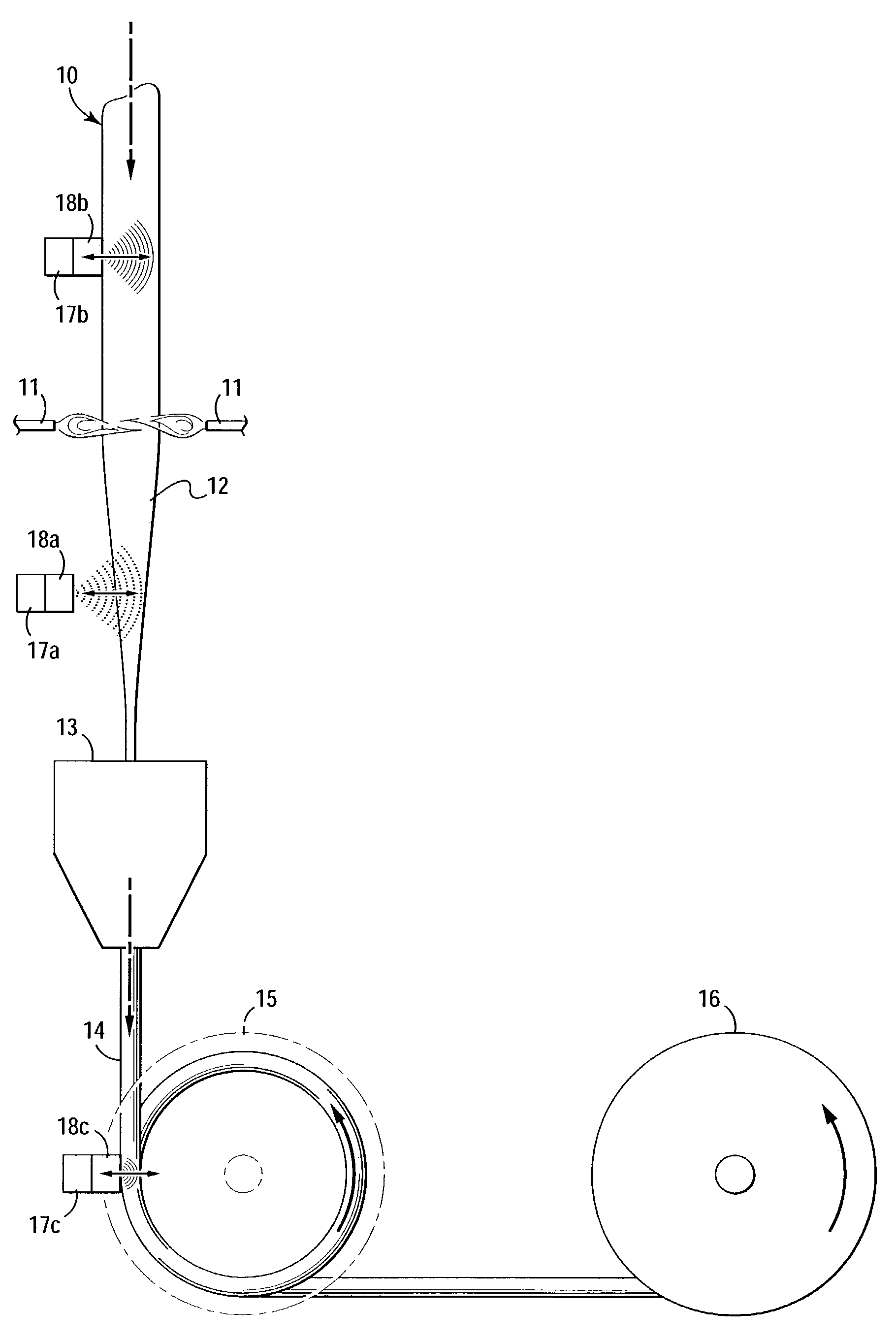
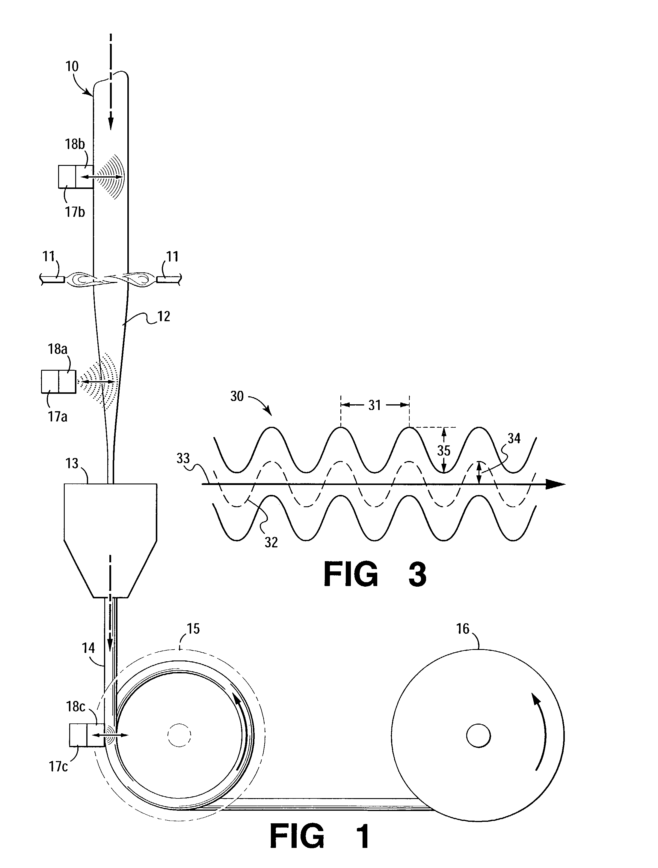
[0077]Multimode fiber, having a 50 μm core of uninterrupted near-2 alpha profile, of matched cladding of undoped silica, containing a continuous axis-perturbation primary perturbation stream of 1000 μm period, is fabricated using the apparatus / method of FIG. 1. Oscillator-transducer 17a / 18a, operating at frequency of 10,000 Hz, with pressure of 2.4 Pascals (Pa) at the fluid surface, produces an acoustic wave of approximately 1 μm amplitude, in the fluid 12 in the vicinity of the fluid-solid draw interface, resulting in a surface undulation of >0.001 μm in the solidified fiber.

example 2

Fabrication of Enhanced Multimode Fiber of Co-pending Patent Application, “Enhanced Multimode Fiber,”

[0078]The procedure of Example 1 is followed, with drawing from a preform with index discontinuity consisting of an annular feature of reduced index of 50% Δ, with inner bound located at 0.7 of the core radius. An additional perturbation stream, of 1300 μm period, is superimposed on the primary stream for stripping the highest order mode group, by introduction of a second acoustic wave. Oscillator-transducer 17a / 18a, operating at dual frequencies—7500 Hz as well as 10000 Hz—with locally attained pressure of 1.5 Pa produces a composite acoustic wave—the composite of two 1 μm waves—as measured in the vicinity of the fluid-solid draw interface, with resulting superimposed surface undulations >0.001 μm in the solidified fiber.

example 3

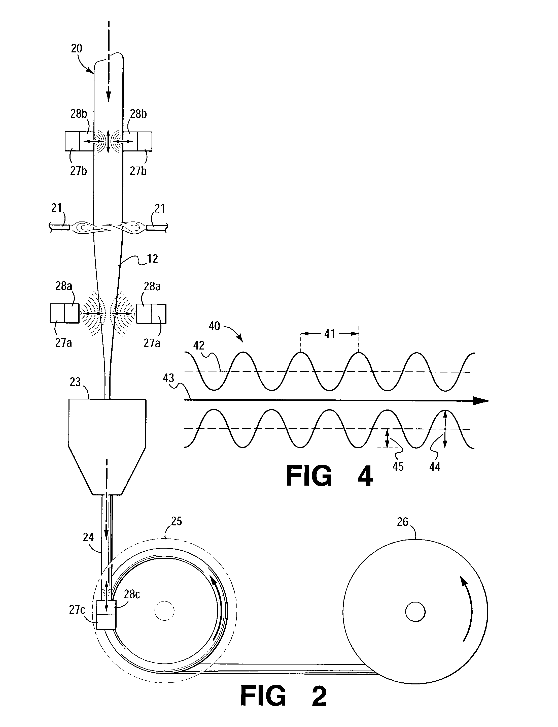
Fabrication of Enhanced Single-Mode Fiber of Co-pending Patent Application “Optical Fiber For Single-Mode Operation,”

[0079]ESMF, for single-mode operation at 1550 nanometers (nm), containing a continuous size-perturbation stream of 700 μm period, is fabricated by use of the apparatus / process of FIG. 2. As described in the co-pending application, provision for single-mode operation over the operating range of 1300-1700 nm requires eliminating many unwanted higher order modes. As there discussed, single-mode operation over that wavelength range is effected by resonantly coupling all such higher order modes to cladding modes. To achieve this over the entire range of 1300-1700 nm requires coupling frequencies over the range of 350-700 μm. Acoustic waves of frequencies spanning the range 17000-34000 Hz are required to achieve such mode stripping. An oscillator-transducer 27a / 28a, operating with all frequencies from 17000-34000 Hz, with pressure of 10-20 Pa as measured at the surface of t...


PUM

PropertyMeasurementUnit
Lengthaaaaaaaaaa
Sizeaaaaaaaaaa
Frequencyaaaaaaaaaa

Abstract

An expeditious method for introducing geometric perturbations into lightguide during fabrication offers a perturbation stream of amplitude and periodicity—constant or varying—to satisfy a variety of needs.

Description

FIELD OF THE INVENTION[0001]Fabrication of lightguide with periodic perturbations for mode coupling.BACKGROUND OF THE INVENTION[0002]The multimode fiber—the initially introduced optical fiber structure expected to dramatically change communications—did not fulfill expectations. The laser-yielded pulse stream to be modulated by signal information, single-mode as introduced at the transmitter, was no longer single-mode as detected at the receiver. Collisions with defects in the glass fiber caused mode conversion, ultimately yielding pulses constituted of photons of a broad spectrum of higher-order modes, extending even beyond those which could be guided by the fiber structure (to “lossy” modes—to modes soon lost by radiation). Consequential mode-dispersion resulted in pulse spreading—with lower order modes at the leading edge of the pulse and higher order at the trailing edge. This restricted the pulse repetition rate of the injected train to the maximum rate with sufficient retained ...

Claims


Application Information

Patent Timeline
IPC IPC(8): C03B37/023C03B37/027G02B6/02G02B6/14
CPCC03B37/027G02B6/02C03B2203/18C03B2203/36G02B6/14Y02P40/57
Inventor HONG, SIU-PINGJACOBS, STEVEN ALANKALISH, DAVIDRITGER, ALBERT JOHNWHITE, IAN A.
Owner FURAKAWA ELECTRIC NORTH AMERICA INC
Why Eureka
Try Eureka