Redox flow battery

a redox flow battery and battery technology, applied in the direction of batteries/cells, non-aqueous electrolyte cells, fuel cells, etc., can solve the problems of insufficient time required for recharging, inconvenient electrical recharging facilities, general inconvenience of automobiles, etc., to improve the charging method of a redox flow battery and improve the redox flow battery

Inactive Publication Date: 2009-05-26
RENEWABLE ENERGY DYNAMICS TECH
View PDF9 Cites 18 Cited by
  • Summary
  • Abstract
  • Description
  • Claims
  • Application Information

AI Technical Summary

Benefits of technology

[0007]The object of the present invention is to provide an improved red

Problems solved by technology

This is generally inconvenient for an automobile.
Further, facilities for electrical recharging are inconvenient in a car park for instance and the time required for recharging may be insufficient when the automobile has been used to close to the extent of its range and the return journey is required to be made shortly after the outwards journey.
It is possible to recharge

Method used


Image

  • Redox flow battery
  • Redox flow battery
  • Redox flow battery

Examples


Embodiment Construction

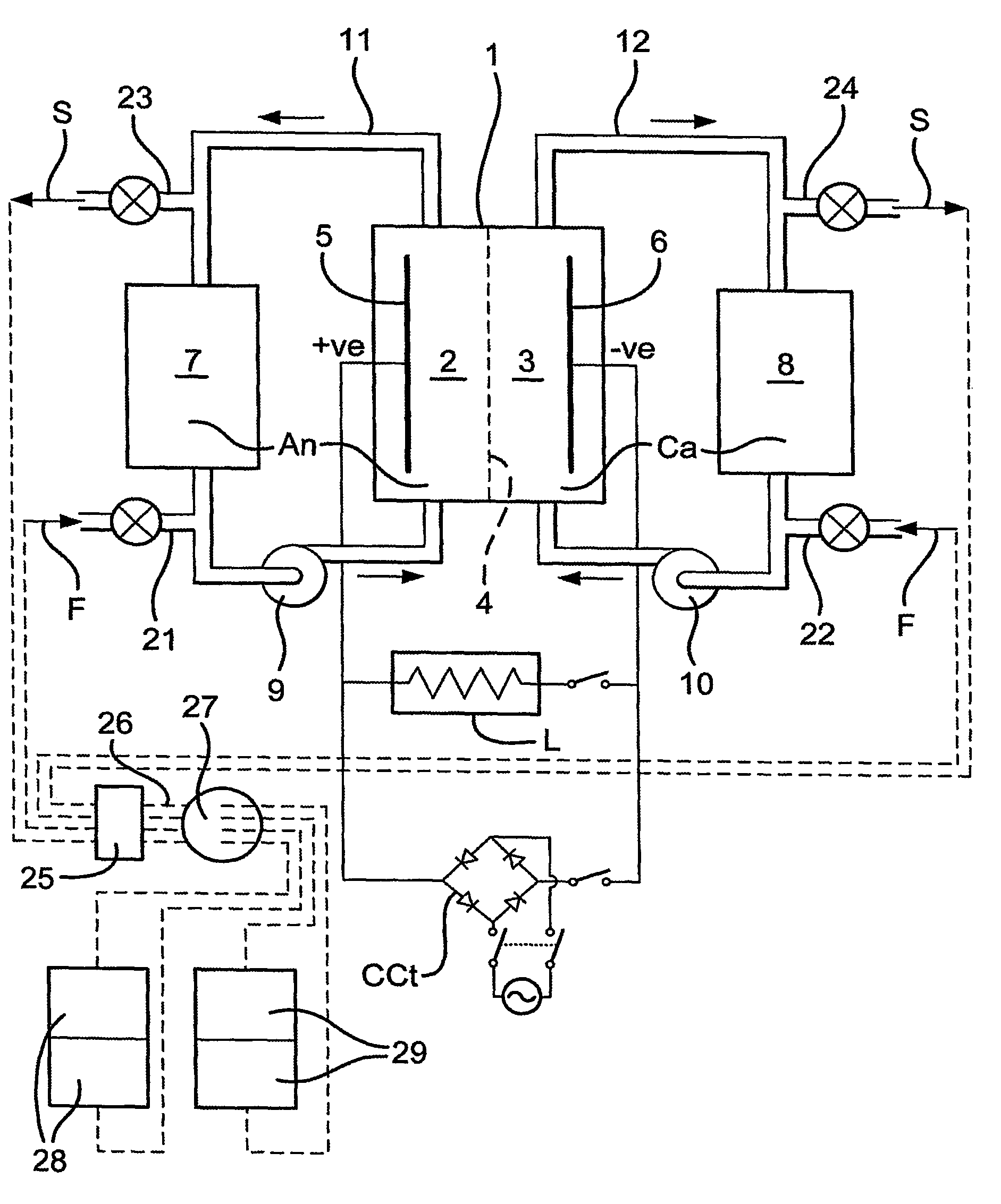
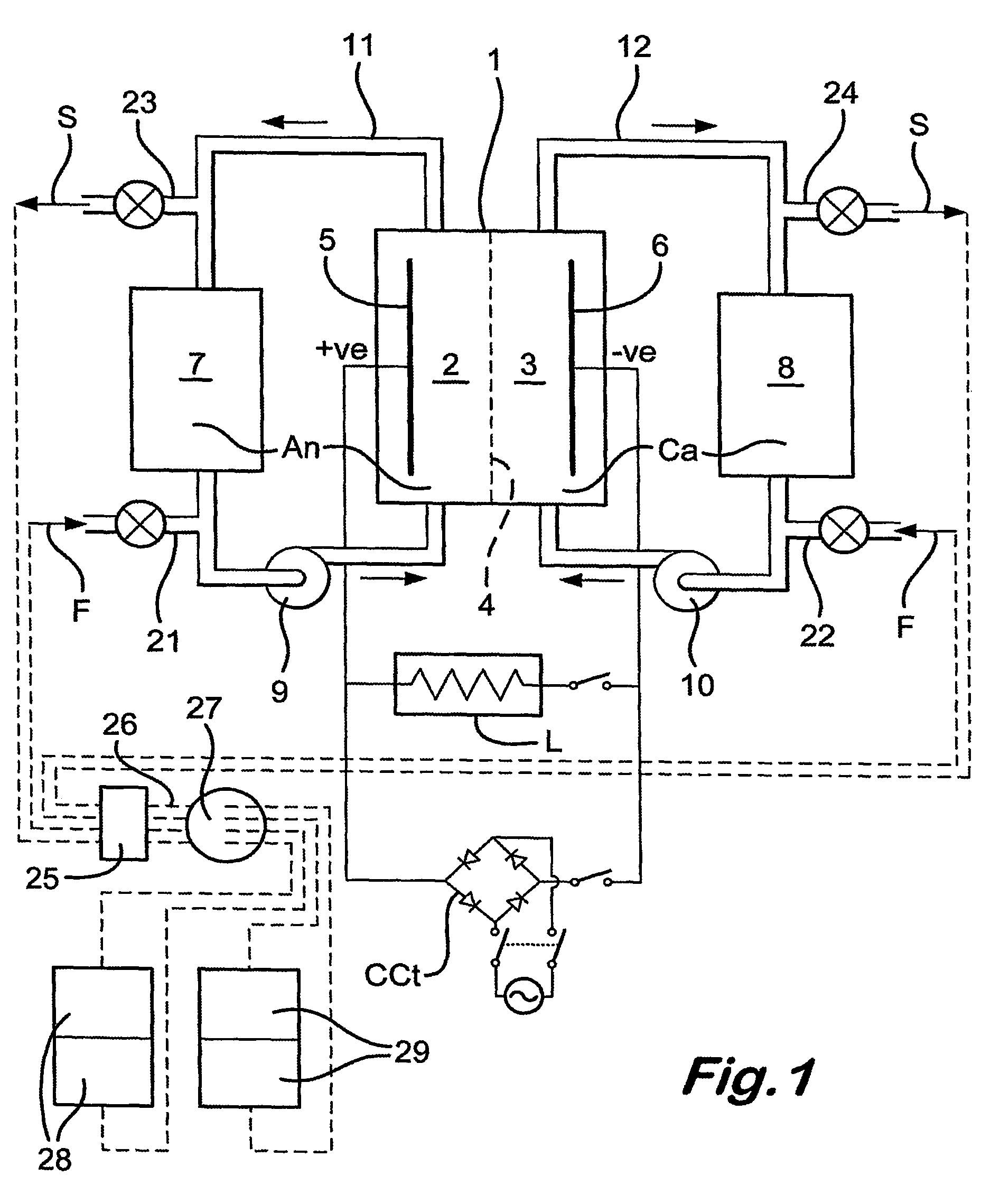
[0032]Referring to the drawings, the redox flow battery illustrated in FIG. 1 has a stack of individual cells, shown diagrammatically as a single cell 1, with anolyte and catholyte compartments 2,3 divided from each other by an ionically selective and conductive separator 4 and having respective electrodes 5,6.

[0033]The preferred battery uses the Vanadium Redox chemistry described in U.S. Pat. No. 4,786,567, to which the reader is referred for a better understanding. However, the chemistry per se forms no part of the present invention, which is not restricted to Vanadium Redox batteries.

[0034]The battery of FIG. 1 has anolyte and catholyte tanks 7,8, with respective pumps 9,10 and a pipework 11,12. In use, the pumps circulate the electrolytes An,Ca to and from the tanks 7,8 to the compartments 2,3 and back to the tanks. Electricity flows to a load L. When the battery is being recharged conventionally, the load is isolated and a charging circuit CCt is switched in. The battery rechar...


PUM


Abstract

A redox flow battery 1 has a stack of individual cells, shown diagrammatically as a single cell, with anolyte and catholyte compartments divided from each other by an ionically selective and conductive separator and having respective electrodes. The battery has anolyte and catholyte tanks, with respective pumps and a pipework. In use, the pumps circulate the electrolytes to and from the tanks, to the compartments and back to the tanks. Electricity flows to a load. The electrolyte lines are provided with tappings via which fresh electrolyte can be added and further tappings via which spent electrolyte can be withdrawn, the respective tappings being for anolyte and catholyte. On recharging, typically via a coupling for lines to all the tappings, a remote pump pumps fresh anolyte and fresh catholyte from remote storages and draws spent electrolyte to other remote storages.

Description

CROSS-REFERENCE TO RELATED APPLICATIONS[0001]This application is for entry into the U.S. national phase under §371 for International Application No. PCT / GB03 / 00658 having an international filing date of Feb. 13, 2003, and from which priority is claimed under all applicable sections of Title 35 of the United States Code including, but not limited to, Sections 120, 363 and 365(c), and which in turn claims priority under 35USC §119 to United Kingdom Patent Application No. GB 0203508.7 filed on Feb. 14, 2002.TECHNICAL FIELD[0002]The present invention relates to a redox flow battery and a method of charging of such a battery.BACKGROUND OF THE INVENTION[0003]In a fuel cell of a redox flow battery, reagents are passed to opposite sides of an ionically selective and conductive membrane separator separating two reagent compartments, electrodes being provided in the respective compartments. In a redox fuel cell, the reagents are an anolyte and a catholyte. Electricity flows between the reagen...

Claims


Application Information

Patent Timeline
IPC IPC(8): H01M4/36H01M2/38H01MH01M2/08H01M8/02H01M8/04H01M8/18H01M8/20H01M10/36
CPCB60L11/1816B60L11/1879H01M8/04119H01M8/04276H01M8/188Y02T90/14Y02E60/528Y02T10/7005Y02T10/705Y02T10/7011B60L50/64Y02E60/10Y02E60/50Y02T10/70H01M8/02H01M8/0215H01M8/18H01M10/36Y02T10/7072
Inventor SAMUEL, JOHN MICHAEL GLENRIDLEY, PETER JOHN
Owner RENEWABLE ENERGY DYNAMICS TECH
Why Eureka
Try Eureka