Method and apparatus for computer-aided determination of viewer's gaze direction

a technology of computer-aided determination and viewer's gaze, applied in the field of contact-free video, can solve problems such as prevailing complexity, and achieve the effects of reducing complexity, reducing discomfort, and maximum precision in measuring the view direction

Inactive Publication Date: 2009-05-26
FRAUNHOFER GESELLSCHAFT ZUR FOERDERUNG DER ANGEWANDTEN FORSCHUNG EV
View PDF21 Cites 74 Cited by
  • Summary
  • Abstract
  • Description
  • Claims
  • Application Information

AI Technical Summary

Benefits of technology

[0014]For that reason, the task of the present invention is to be seen in providing an improved method with integrated calibration and, more particularly, recalibration for correcting systematic errors of measurement, relative to the prior art, of determining a view direction and which ensures both a maximum precision for measuring the view direction and minimum discomfort to the user. Moreover, it is a task of the invention to allow use of the view direction measuring system for a plurality of individual users without subjecting them to the calibration process. In addition to reducing the complexity for individual users, the complexity of the measuring system is also to be reduced so that calibration may be performed without complex mathematical processes or additional elaborate system components.

Problems solved by technology

To be sure, the prevailing complexity corresponds to the complexity of known methods with a time-dependent fixation of different arbitrary calibration points taking into account all system and process parameters.

Method used


Image

  • Method and apparatus for computer-aided determination of viewer's gaze direction
  • Method and apparatus for computer-aided determination of viewer's gaze direction
  • Method and apparatus for computer-aided determination of viewer's gaze direction

Examples


Embodiment Construction

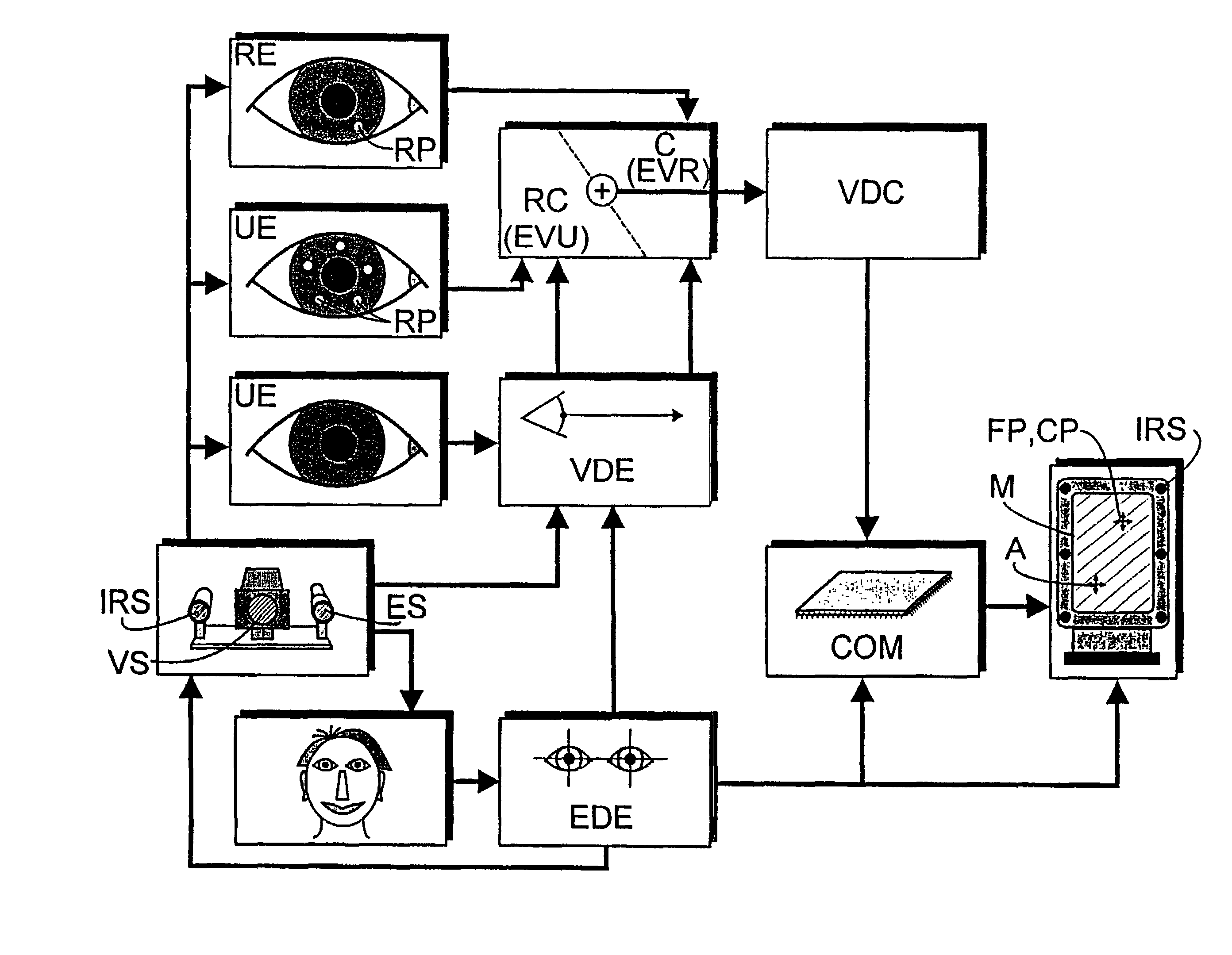
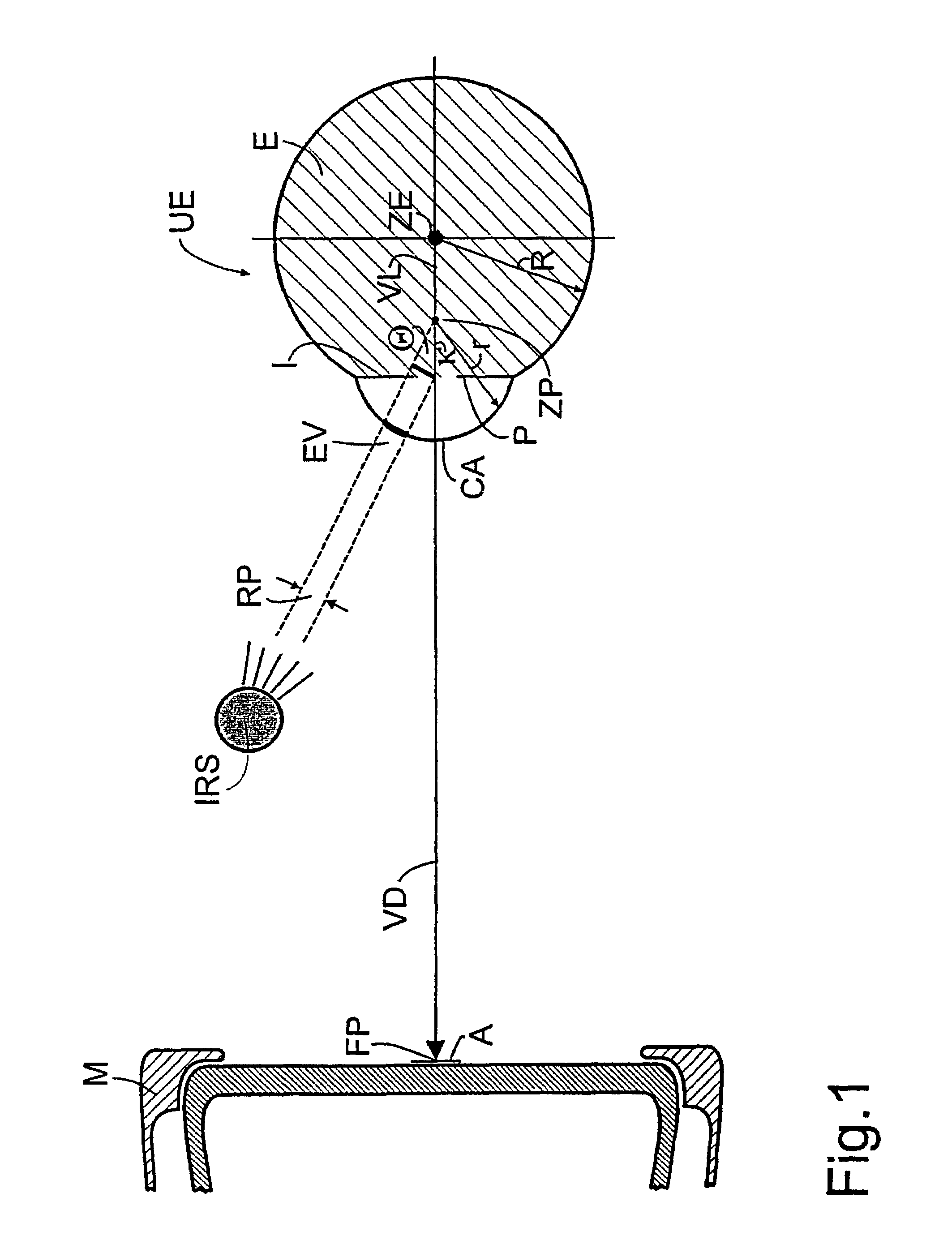
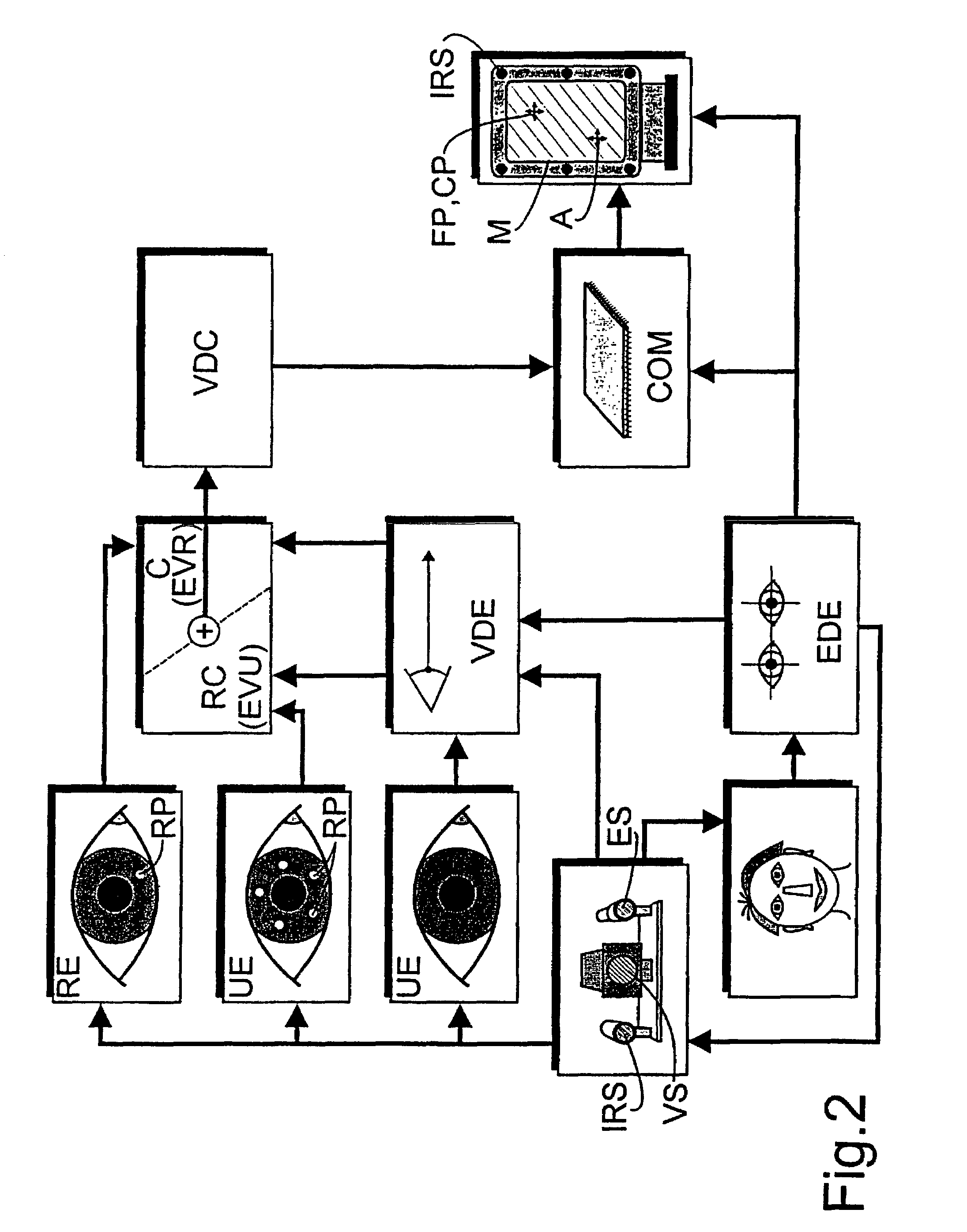
[0028]FIG. 1 depicts a simplified model for describing the human eye on the basis of which the basic concepts of the process in accordance with the invention proceeding on the cornea-reflex-method are to be described in greater detail. The eyeball E is an approximate sphere having a fulcrum ZE. The cornea (Cornea CA) is positioned at the forward side of the eyeball E, and its surface is spherically shaped and is of radius r. The iris I is modeled as a circular disc having a central aperture (Pupille P). The optical axis of the eye E connects the fulcrum ZE of the eyeball with the center ZP of the pupil P and is called visual axis VL the direction of which (it points from the fulcrum ZE to the center ZP of the pupil) defines the view direction VD. When the view direction VD is changed the eyeball E rotates about its fulcrum ZE. The fixation point FP is the intersection of the visual axis VL of an eye E and the surface of the viewed icon A. In normal dual eye vision the fixation point...


PUM


Abstract

The corneal reflex method is used to detect the current direction of view (VD) of a user (UE) to perform specifically selected functions on a computer. Eye vectors (EV) can be detected between the pupil center (ZP) and reflection points (RP) on the cornea (CA) that can be associated with a fixation point (FP) on a computer screen using infrared light (IRS). The association is produced as a function of the direction of view (VDF), so the relationship is detected during an initial calibration (C) by a referenced user (RE) to develop a set of reference eye vectors (EVR). A shorter self-balancing recalibration (RC) is then carried out for each subsequent user (UE). A mapping function (MF) is detected during the recalibration (RC) so that the individual eye vectors (EVU) can be converted to the reference eye vectors (EVR) by the mapping function. The recalibration (RC) can take place without the user (UE) realizing it. The method is useful in medical diagnostics, psycho-optical examinations and eye-controlled interaction with multimedia computers.

Description

BACKGROUND OF THE INVENTION[0001]1. Field of the Invention[0002]The invention relates to a computer-aided method of contact-free video-based determination of the direction of view of an eye of a viewer for the eye-controlled man-computer interaction in accordance with the cornea reflex method of detecting view-direction dependent eye vectors between the detectable center of the pupil and reflex points which are generated on the cornea by aimed infra red irradiation and which can also be detected, with calibration with respect to at least one calibration point which can be depicted on a video screen for defining a view direction function and a recalibration to be performed in dependence of the generation of image objects and a plurality of reflex points for correcting systematic errors of measurement, and to an apparatus for practicing the method.[0003]2. The Prior Art[0004]The continuing integration of information technological systems offers computer users a wide spectrum of novel ...

Claims


Application Information

Patent Timeline
Patent Type & Authority Patents(United States)
IPC IPC(8): G09G5/00A61B3/10G06F3/00G06F3/01
CPCG06F3/013
Inventor LIU, JINPASTOOR, SIEGMUND
Owner FRAUNHOFER GESELLSCHAFT ZUR FOERDERUNG DER ANGEWANDTEN FORSCHUNG EV
Why Eureka
Try Eureka