
Method of microscopically examining a spatial finestructure

a microscopy and fine structure technology, applied in the field of microscopy examining a spatial fine structure, can solve the problems of unable to apply known methods to check, possible to take lost samples, and fine structures which have been examined electron-microscopically have to be discarded, etc., to achieve high spatial resolution and high spatial resolution

Inactive Publication Date: 2009-05-26
MAX PLANCK GESELLSCHAFT ZUR FOERDERUNG DER WISSENSCHAFTEN EV
View PDF7 Cites 20 Cited by
  • Summary
  • Abstract
  • Description
  • Claims
  • Application Information

AI Technical Summary

Benefits of technology

This approach enables high spatial resolution microscopy of fine structures down to 80 nm width and 40 nm distance without damaging the samples, allowing for the examination of fine structures in final products and reducing the risk of faulty device production by enabling the removal of the luminophore after analysis.

Problems solved by technology

Additionally, it has to be regarded as a disadvantage that the fine structures which have been examined electron-microscopically have to be discarded because of their irreversible coating with aluminium.
I.e. the known method cannot be applied to check a fine structure which is as such also present in a final product.
Instead, it is only possible to take lost samples.
At present, very few alternatives to electron-microscopic examination are available in the lithographic production of fine structures, if a resolution in the range of less than 150 nm is to be obtained.
Atomic Force Microscopy (AFM) and Scanning Near Field Optical Microscopy (SNOM) belong to these methods, which on the one hand need no high vacuum, but which are on the other hand dependent on an exact and thus laborious adjustment of the clean fine structure with regard to the sensible arrangement for moving the respective probe, and which are thus extremely slow as compared to the size of the fine structure to be examined.
This, however, essentially increases the danger of faultily produced electric devices.

Method used


Image

  • Method of microscopically examining a spatial finestructure
  • Method of microscopically examining a spatial finestructure
  • Method of microscopically examining a spatial finestructure

Examples


Embodiment Construction

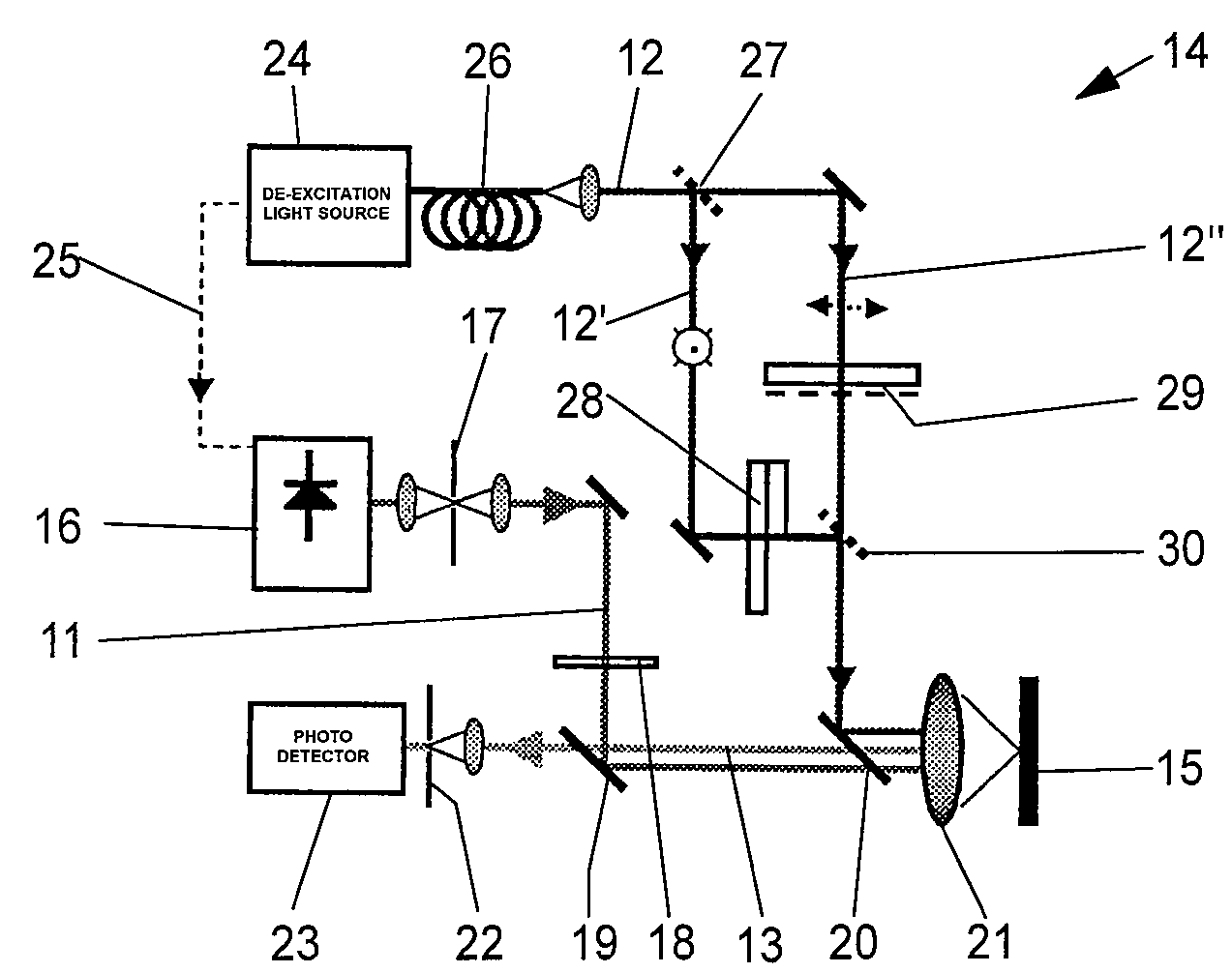
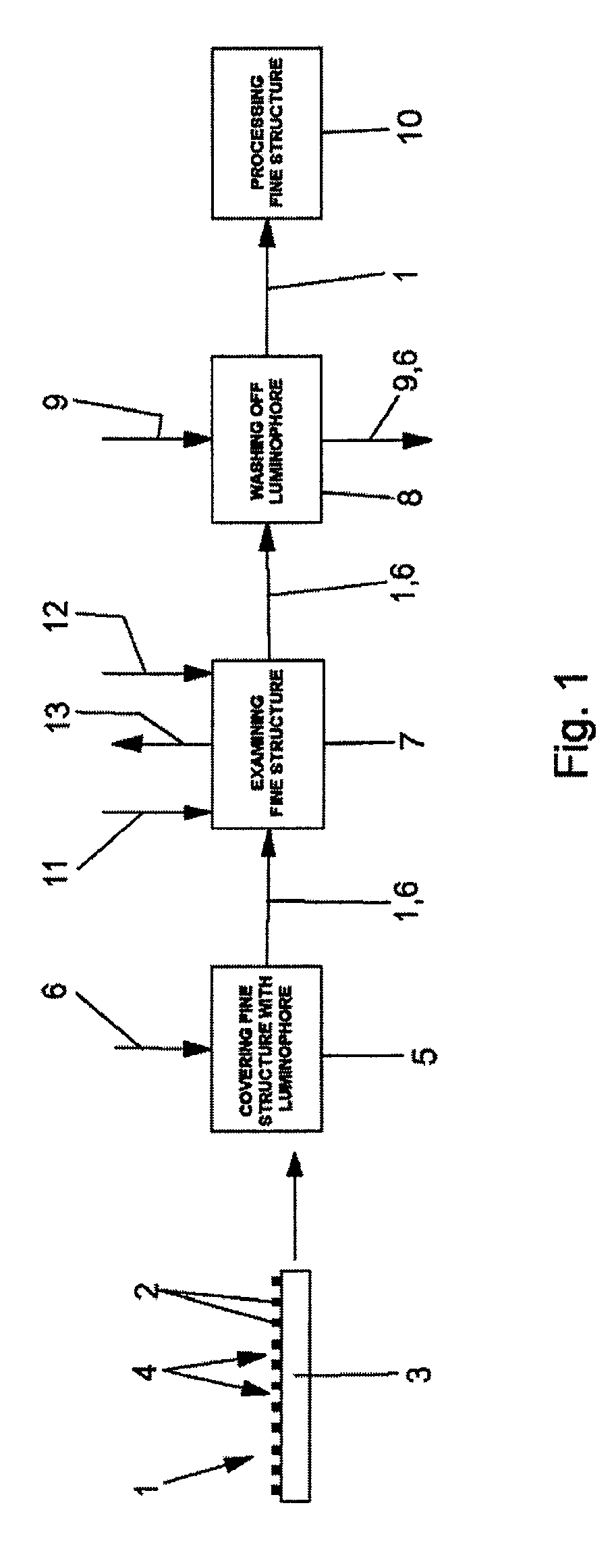
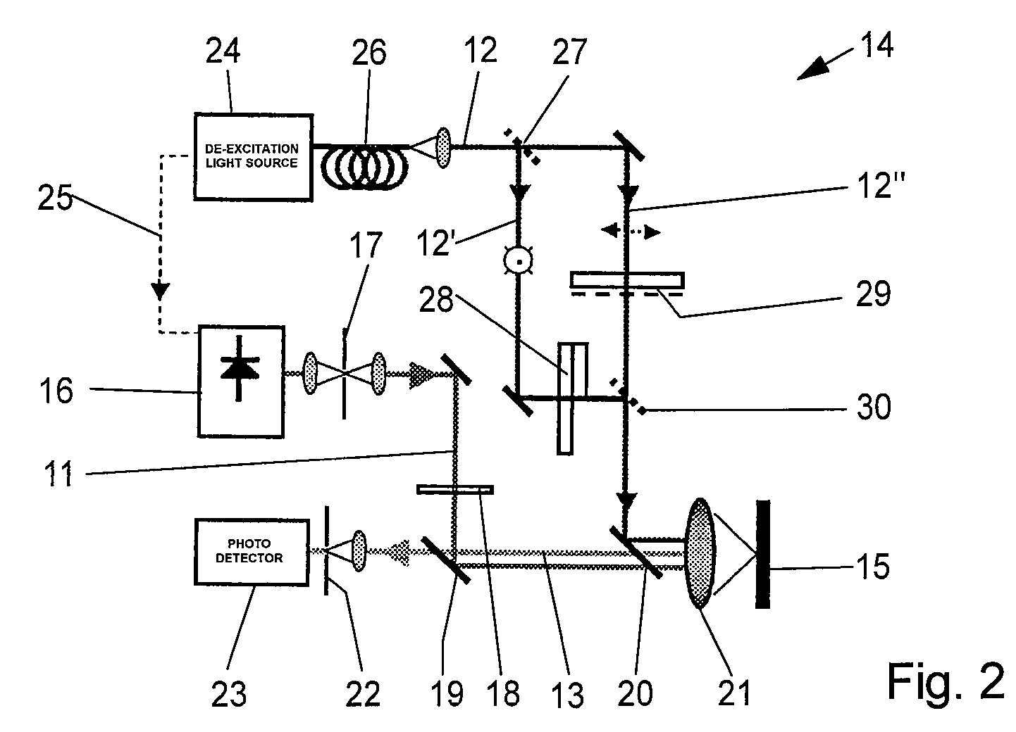
[0035]Referring now in greater detail to the drawings, FIG. 1 outlines a method of microscopically examining a spatial fine structure 1, which is indicated as a pattern of line-shaped elevations 2 above a substrate 3. The fine structure 1 can be the result of a lithographic process which is not described in further detail here. In a first method step 5 the surface 4 of the fine structure 1 is overlaid with a luminophore 6 which enables its microscopic examination. To this end, the luminophore 6 is evaporated so that it is uniformly deposited on the surface 4. In a next method step 7, the fine structure 1 covered with the luminophore 6 is microscopically examined. Here, the luminophore 6 which is a fluorescence dye is excited by a beam of excitation light 11 for fluorescence, but de-excitated again by a beam of de-excitation light 12 through stimulated emission except of in the present measurement points of interest. Thus, only fluorescence light 13 which originates from the remainin...


PUM


Abstract

A method of microscopically examining a spatial fine structure comprises the steps of selecting a luminophore from the group of luminophores which have two physical states, the two states differing from each other with regard to the luminescence properties displayed by the luminophore, and which are reversibly, but essentially completely transferable out of one into the other state of their two states by means of an optical signal; overlaying a surface of the spatial fine structure with the luminophore; and determining the profile of the surface overlaid with the luminophore. The step of determining the profile of the surface comprises the sub-steps of transferring the luminophore by means of the optical signal out of the one into the other of its two states outside a presently observed measurement point, measuring luminescence light emitted by the luminophore, and repeating the sub-steps of transferring and measuring for further measurement points distributed over the surface.

Description

CROSS REFERENCE TO RELATED APPLICATIONS[0001]This application is a continuation in part of International Patent Application PCT / EP2006 / 002711 entitled “Verfahren zur mikroskopischen Untersuchung einer räumlichen Feinstruktur”, filed on Mar. 24, 2006, and claiming priority to co-pending German Patent Application No. DE 10 2005 013 969.8 also entitled “Verfahren zur mikroskopischen Untersuchung einer räumlichen Feinstruktur”filed Mar. 26, 2005.FIELD OF THE INVENTION[0002]The invention generally relates to a method of microscopically examining a spatial fine structure. More particularly, the comprising the invention relates to a method of microscopically examining a spatial fine structure, the method comprising the steps of coating a surface of the spatial fine structure with an auxiliary agent, and microscopically determining the profile of the surface coated with the auxiliary agent.[0003]The fine structure can be an artificial, i.e. a man-made fine structure. For example, the spatia...

Claims


Application Information

Patent Timeline
Patent Type & Authority Patents(United States)
IPC IPC(8): G01B11/24
CPCG01N21/643G01N21/6458
Inventor HELL, STEFANWESTPHAL, VOLKERQUAAS, NORBERT
Owner MAX PLANCK GESELLSCHAFT ZUR FOERDERUNG DER WISSENSCHAFTEN EV
Learn More