Detector for charged particle beam instrument

a technology of charged particle and detector, which is applied in the field of electron microscope, can solve the problems of limiting the detector space, difficult to accommodate an in-lens pla within pole pieces having a 2 mm bore, and the configuration shown in fig. 1 is more difficult to implement in systems optimized for coincident electron and ion beams, so as to improve detection, increase the distance of secondary electron travel, and increase the number of collisions

Active Publication Date: 2009-06-02
FEI CO
View PDF19 Cites 22 Cited by
  • Summary
  • Abstract
  • Description
  • Claims
  • Application Information

AI Technical Summary

Benefits of technology

[0006]In an HPSEM, the sample that is to be investigated is placed in an atmosphere of a gas having a pressure typically between 0.1 Torr (13 Pa) and 50 Torr (7000 Pa), and more typically between 1 Torr (130 Pa) and 10 Torr (1,300 Pa) whereas in a conventional SEM the sample is located typically in a vacuum of about 10−6 Torr (1.3×10⁻⁶ mbar). Unlike a conventional SEM, an HPSEM can readily form electron-optical images of moist or non-conducting samples, such as biological samples, plastics, ceramic materials and glass fibers, which would be difficult to image under the typical vacuum conditions of a conventional SEM. The HPSEM allows samples to be maintained in their natural state, without being subjected to the disadvantageous effects of drying, freezing or vacuum coating, which are normally necessary in studies of such samples using conventional SEMs. The gaseous atmosphere of an HPSEM sample chamber provides inherent charge neutralization, that is, the dissipation of surface charge that accumulates on a non-conductive sample as a result of irradiation. Dissipating surface change increases resolving power of the microscope.
[0007]The gaseous atmosphere in an HPSEM also makes improved detection means possible. In an HPSEM, the liberated secondary electrons that move in the direction of the secondary electron detector will collide en route with gas molecules in their path. This collision will result in the liberation of new electrons, referred to as “daughter electrons,” from the gas molecules. The daughter electrons will also move in the direction of the secondary electron detector. In their turn, these newly liberated daughter electrons will again collide with other gas molecules, and so forth, so that an amplification of the secondary electron signal occurs. The term secondary electron is used to include daughter electrons and reflected primary beam electrons, was well as electrons emitted directly from the sample. The greater the distance that the secondary electrons travel to the secondary electron detector, the greater the number of collisions that will occur between secondary electrons and gas molecules and so the greater the amplification achieved. On the other hand, it is desirable that the primary beam path through the pressurized sample chamber be as short as possible because the gas molecules present scatter the primary beam electrons.
[0008]Japanese patent publication 5-174768(A) describes an HPSEM wherein the primary beam from the particle source is focused on the sample by a magnetic immersion lens. The immersion lens consists of a magnetic dipole having poles located on opposite sides of the sample. The magnetic field will cause the secondary electrons liberated from the sample to follow a helical path on their way to the detector. It is claimed that in this way, the distance traversed by the secondary electrons is increased, so that the collision probability increases proportionately and the amplification factor of the detection apparatus increases.
[0009]In the configuration described in JP5-174768(A) the electrons follow a helical path around an axis that extends parallel to a magnetic field. The distance traversed by the electron from the sample to the detector is directly dependent upon the distance between the detector and the sample in the direction of the magnetic field. The detector electrode should be therefore be located as high as possible above the sample, so as to achieve as large an amplification factor as possible. Consequently, the distance traversed by the primary beam through the gaseous atmosphere will also be large, and scattering of the primary beam will increase. An increased amplification factor for the detection apparatus is thus achieved at the expense of the resolving power of the illustrated device.
[0010]An improved environmental scanning electron microscope is described in U.S. Pat. No. 6,972,412 for “Particle-Optical Device and Detection Means,” to Scholtz et al. (Scholtz), which is hereby incorporated by reference and which is assigned to FEI Company, the assignee of the present invention. In the invention of Scholtz, a portion of the detector volume includes an electric field having a component parallel to the magnetic field, and a portion has an electric field having a component perpendicular to the magnetic field. Secondary electrons are subjected to both axial oscillations (i.e., the Penning effect, also referred to as the “yo yo” effect), and radial oscillations (i.e., the “magnetron” effect). These oscillations greatly increase the secondary electron path length, and hence the number of collisions with gas molecules, thereby increasing the amplification of the secondary electron signal. The electric and magnetic fields are such to assure that a significant number of electrons in the detector space have sufficient energy to ionize the gas molecules.
[0011]FIG. 1 shows an example of an improved HPSEM 100 using a detector 102 in accordance with the principals of Scholtz. In a sample chamber 104, an electrode assembly 106 is attached to the bottom of pole piece support 108 that supports a pole piece 110 of a lens 112. The electrode assembly 106 includes an anode 120, an ion trap 122, and a pressure limiting aperture electrode 124 having a hole that defines a pressure limiting aperture, PLA 126. Insulating spacers 128 separate the various electrodes. A primary electron beam 134 is directed through PLA 126 toward a sample 136 positioned on a movable sample stage 138. A gas is introduced into sample chamber 104 from a gas source 140. Secondary electrons are emitted from the sample 136 upon impact of the primary beam 134. The secondary electrons are accelerated toward the anode 120, and preferably undergo a combination of magnetron and penning oscillation. The secondary electrons lose energy as they collide with the gas molecules are eventually collected by the anode 120. Ionized gas molecules are collected by the ion trap 122, the sample 136, and the PLA 126. Secondary electrons have the distance, d, available between the sample and the PLA electrode to create additional electrons by collisions with gas molecule. In the detector described by Scholtz, the PLA is flush with the bottom of the pole piece. The secondary electrons therefore have only the distance, d2, available to create additional electrons by collisions with gas molecule. By positioning the PLA inside the lens, the improved configuration provides additional detector space in which the gas can be ionized to amplify the secondary electron signal, without increasing the working distance, that is, the distance between the lens and the sample. Although positioning the PLA inside the lens provides additional detector space, there are still some disadvantages to the embodiment shown in FIG. 1.

Problems solved by technology

Although positioning the PLA inside the lens provides additional detector space, there are still some disadvantages to the embodiment shown in FIG. 1.
1. The height of the active part of the detector volume, while extended compared to the original Scholtz configuration, is still limited by the distance “d” between the sample and the PLA, thereby limiting the detector space.
3. While the detector geometry shown in FIG. 1 is useful, for example, in an electron column in which the pole pieces have a 4 mm bore, it is difficult to accommodate an in-lens PLA within pole pieces having a 2 mm bore.
Also, the configuration shown in FIG. 1 is more difficult to implement in systems optimized for coincident electron and ion beams.
Consequently, said electrons will not be available to participate further in the amplification process or to be collected by the anode as part of the detection current.
Similarly, if the height of the yo yo oscillation about the anode described by Scholtz causes secondary electrons to contact the PLA, those secondary electrons will not be available to participate further in the amplification process or to be collected by the anode as part of the detection current.
That is, the amplification space can be effectively doubled, but that increase is still too small to prevent the loss of a significant fraction of secondary electrons to the sample under conditions of low pressure and short working distance.
When the beam is unblanked, that is, when the beam is re-directed to the sample, the beam tends to drift for a short period of time.

Method used


Image

  • Detector for charged particle beam instrument
  • Detector for charged particle beam instrument
  • Detector for charged particle beam instrument

Examples


Embodiment Construction

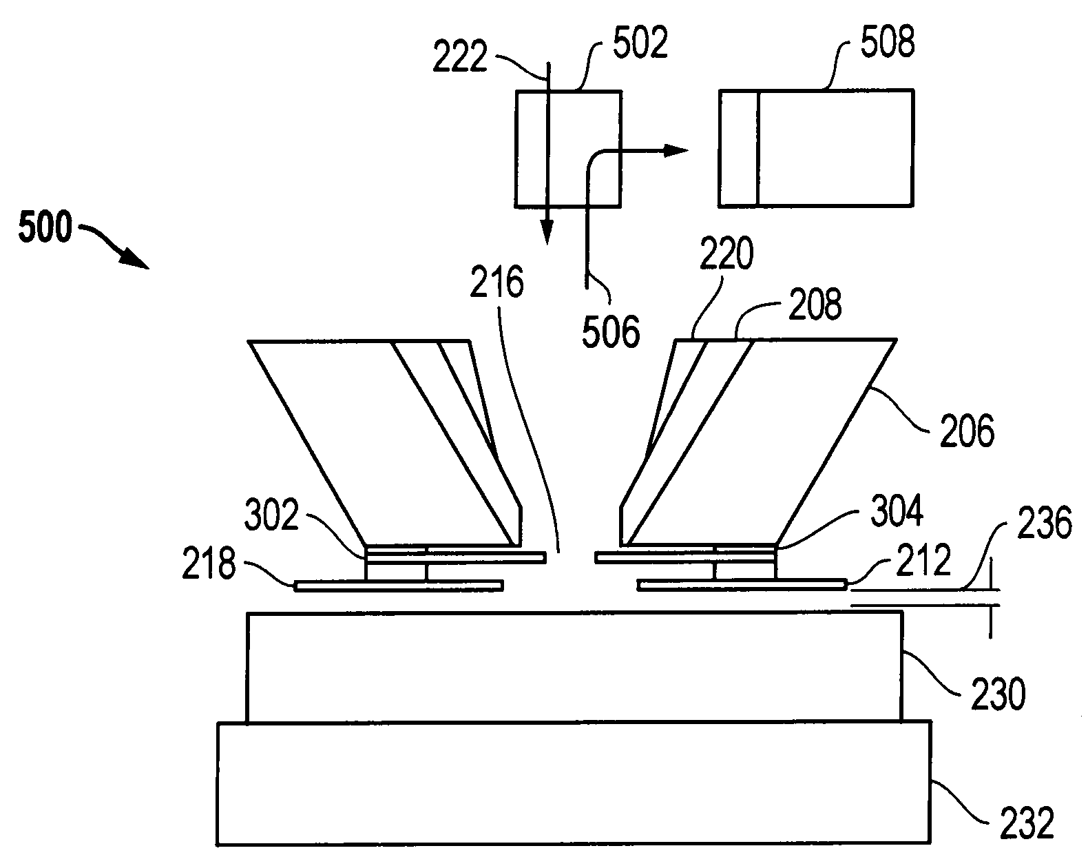
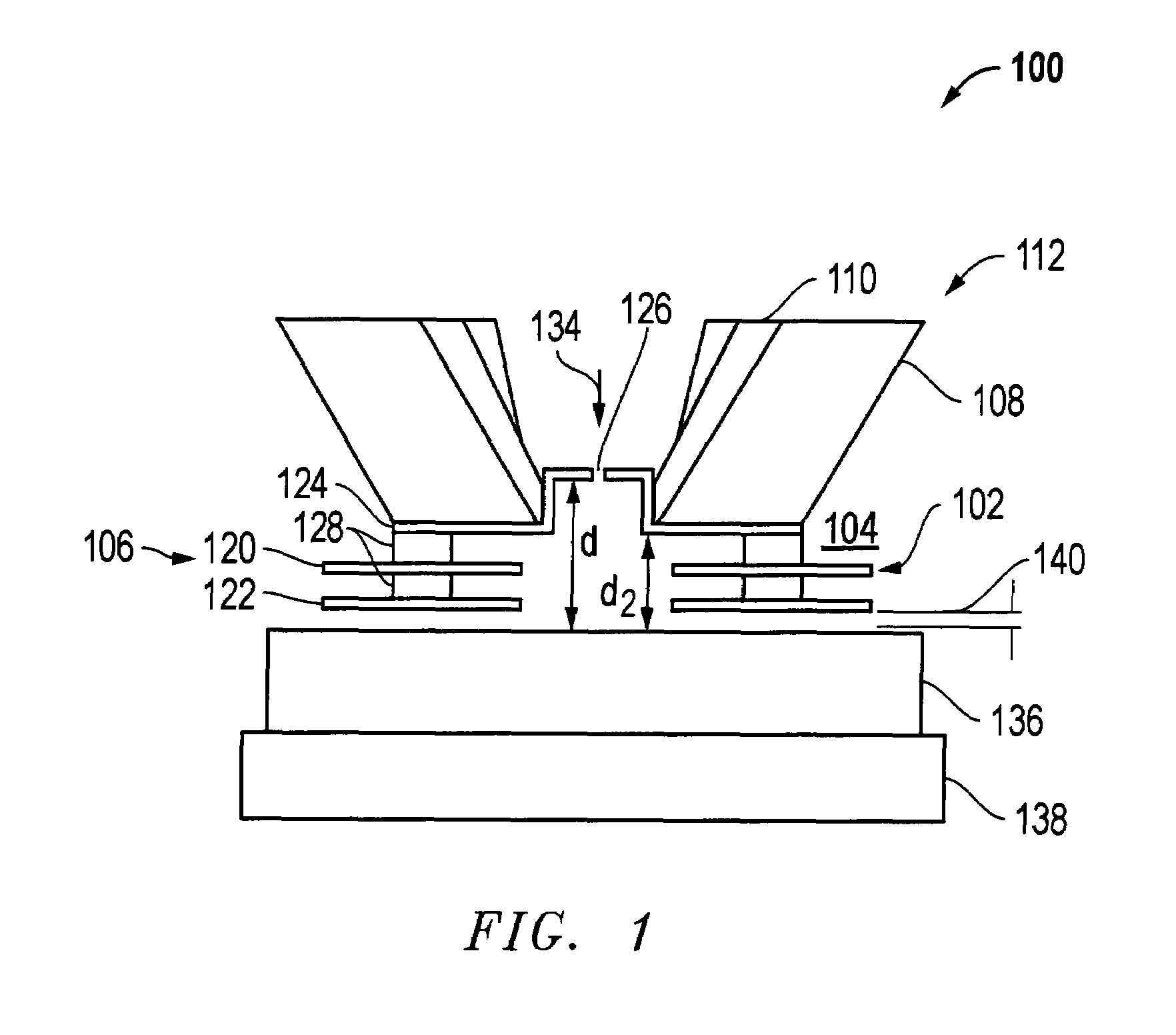
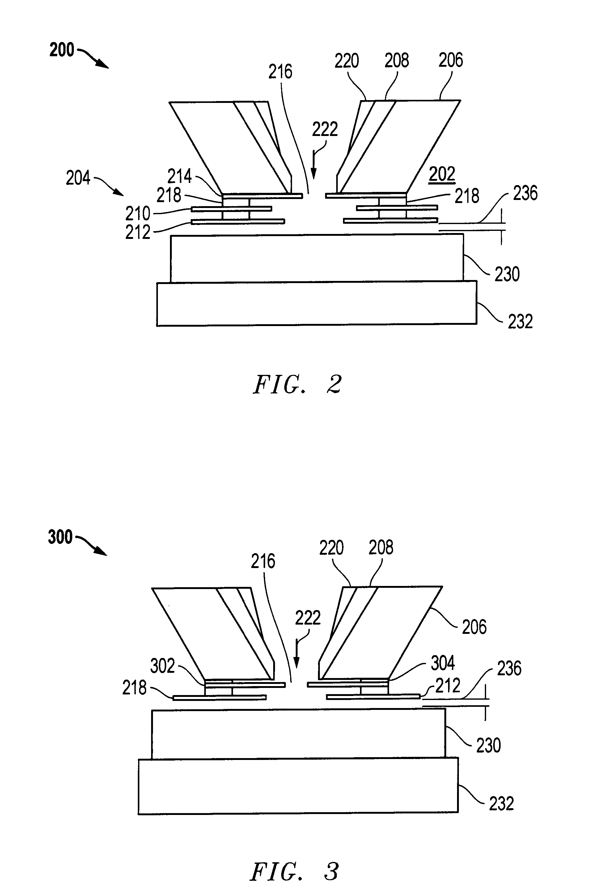
[0027]Embodiments of the present invention increases the active detector space by extending the space available for electron motion through the PLA and into the pole piece, thereby increasing the effective detector space without increasing the working distance. Detector performance limitations imposed by the distance between the sample and the PLA are therefore eliminated. Because the detector space can be larger than the working distance, it is not necessary to have a large working distance to provide a sufficient detector space, and embodiments of the invention therefore permit a column design having a shorter working distance which improves resolution.

[0028]By increasing the efficiency of the gas amplification, embodiments of the invention permit operation at reduced pressures. In some embodiments of the present invention, the PLA diameter is increased compared to a typical PLA diameter of a prior art system, which allows more secondary electrons to pass through the PLA. An elect...


PUM


Abstract

A detector for use with a high pressure SEM, such as an ESEM® environmental SEM from FEI Company, extends the effective detection space above the PLA, thereby increasing secondary signal amplification without increasing working distance or pressure. Embodiments can therefore provide improved resolution and can operate at lower gas pressures.

Description

[0001]This application which claims priority from U.S. Provisional Pat. App. 60 / 787,847, filed Mar. 31, 2007, which is hereby incorporated by reference.TECHNICAL FIELD OF THE INVENTION[0002]The present invention relates to electron microscopes.BACKGROUND OF THE INVENTION[0003]In a scanning electron microscope (SEM), a region of a sample that is to be investigated is probed by a primary beam of electrons that move along an optical axis of the device. The electrons incident on the sample liberate other charged particles from the sample. The energy of these secondary particles, which is substantially lower than the energy of the particles in the primary beam, provides information on the nature, structure and composition of the sample. For this reason, an SEM is often provided with a secondary particle detection apparatus to detect these liberated particles. Conventional SEMs operate in a vacuum to prevent gas molecules from scattering the primary beam and interfering with the collectio...

Claims


Application Information

Patent Timeline
Patent Type & Authority Patents(United States)
IPC IPC(8): H01J37/252
CPCG01N23/225H01J37/244H01J37/28H01J2237/2608H01J2237/2449H01J2237/2003
Inventor KNOWLES, WILLIAM RALPHTOTH, MILOS
Owner FEI CO
Why Eureka
Try Eureka