Optical tomography method and optical tomography system

a tomography system and optical tomography technology, applied in the field of optical tomography methods and optical tomography systems, can solve the problems of high output power of light sources, inability to accurately obtain tomographic images, and inability to satisfy relations with changes

Active Publication Date: 2009-06-02
FUJIFILM HLDG CORP +1
View PDF16 Cites 78 Cited by
  • Summary
  • Abstract
  • Description
  • Claims
  • Application Information

AI Technical Summary

Benefits of technology

[0010]In view of the foregoing observations and description, the primary object of the present invention is to provide an optical tomography method which can stably obtain an accurate tomographic image even if there is disturbance of the spectral shape of the measuring light or change with time of the spectral shape and the intensity of the measuring light.
[0036]In accordance with the optical tomography method of the present invention, since the spectral components of the measuring light is removed from the interference signal obtained by detecting the interference light to obtain the compensating signal and the compensating signal undergoes a Gaussian transform, the signal after the Gaussian transform is basically in the form where the interference components are superposed on a signal of a Gaussian waveform irrespective of the spectral components included in the actual measuring light. Accordingly, when the signal after a Gaussian transform is provided for detection of the intensities of the reflected light, an accurate tomographic image can be stably obtain even if there is disturbance of the spectral shape of the measuring light or change with time of the spectral shape and the intensity of the measuring light.
[0037]Further, when the Gaussian transform is effected after removing noise components due to said division included in the compensating signal, generation of pseudo signals due to the noise when the intensities of the reflected light are detected can be prevented and generation of an incorrect tomographic image can be prevented. Further, by instead detecting the intensities of the reflected light after removing noise components due to said division included in the signal after a Gaussian transform, a similar result can be obtained.

Problems solved by technology

However, depending upon the characteristics of the light source, the relation cannot be originally satisfied or the relation comes to be unable to be satisfied with change with time.
Fluctuation in the intensity of the measuring light leads to errors in measurement of information on the reflection from the object, and fluctuation of the spectral shape generates a pseudo signal in the interference signal due to generation of a side lobe.
However, broadness and high output power of the light source are apt to involve disturbance of the spectral shape of the measuring light or change with time of the spectral shape and the intensity of the measuring light.
Even if broadness and high output power of the light source can be realized, if such a problem is involved, an accurate formation of a tomographic image is difficult due to generation of the pseudo signal described above.

Method used


Image

  • Optical tomography method and optical tomography system
  • Optical tomography method and optical tomography system
  • Optical tomography method and optical tomography system

Examples


first embodiment

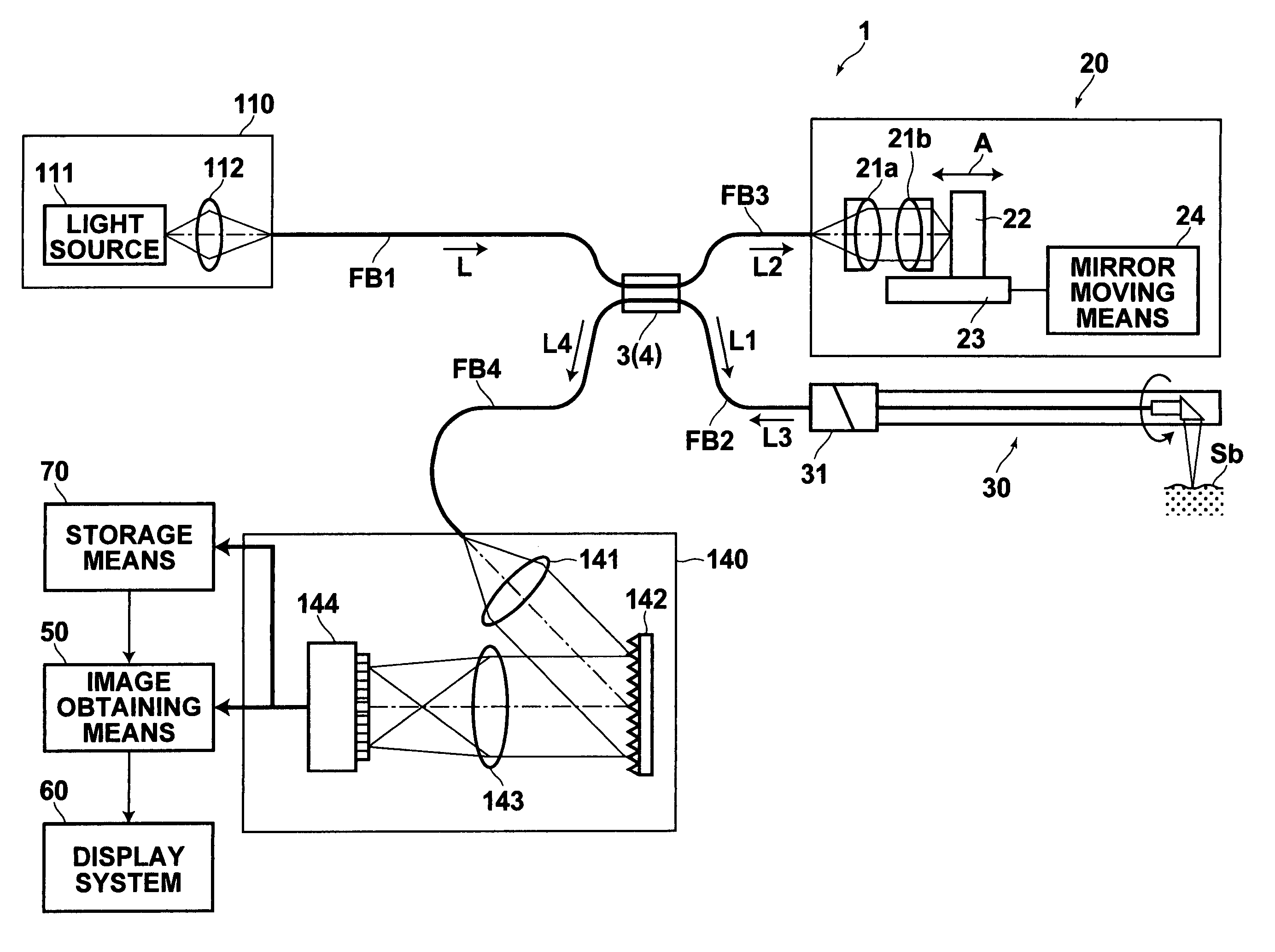
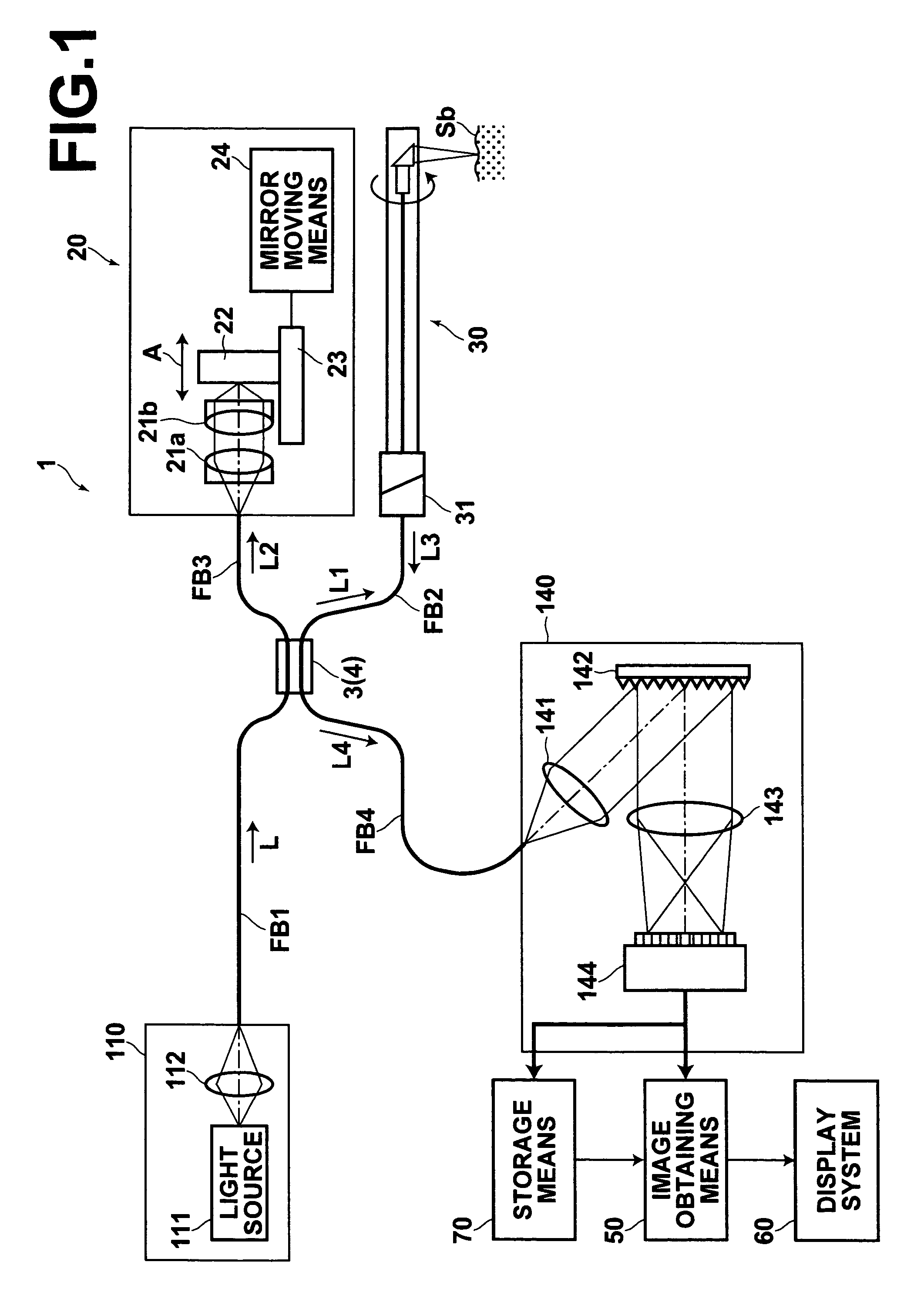
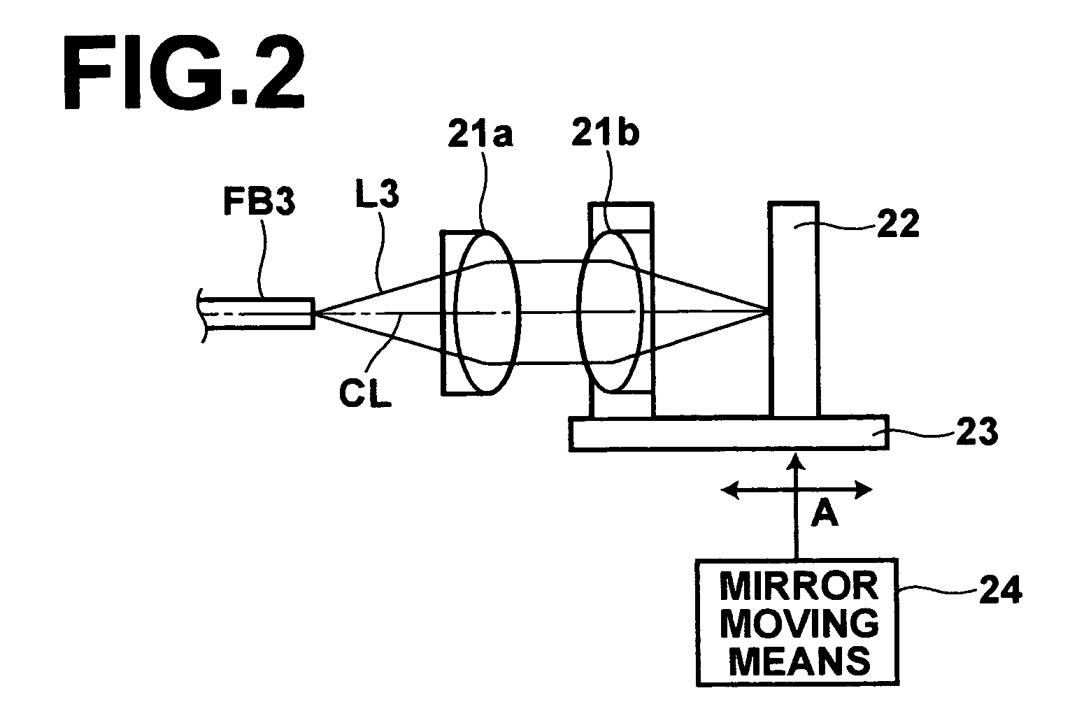
[0057]Embodiments of the present invention will be described in detail with reference to the drawings, hereinbelow. FIG. 1 is a schematic diagram that illustrates an optical tomography system in accordance with the present invention. The optical tomography system 1 of this embodiment is for obtaining a tomographic image of an object of measurement such as a living tissue or a cell in a body cavity by measuring the SD-OCT. The optical tomography apparatus 1 of this embodiment comprises: a light source unit 10 for emitting a light beam L; a light dividing means 3 for dividing the light beam L emitted from the light source unit 10 into a measuring light beam L1 and a reference light beam L2; an optical path length adjusting means 20 for adjusting the optical path length of the reference light beam L2 divided by the light dividing means 3; an optical probe 30 that irradiates the measuring light beam L1 divided by the light dividing means 3 onto the object Sb; a multiplexing means 4 for ...

second embodiment

[0096]An optical tomography system in accordance with the present invention will be described next with reference to FIG. 10. The optical tomography system 100 of this embodiment obtains a tomographic image through measurement of SS-OCT and specifically differs from the optical tomography system 1 shown in FIG. 1 in the structure of the light source unit and the interference light detecting means. In FIG. 10, the elements analogous to those shown in FIG. 1 are given the same reference numerals and will not be described unless necessary.

[0097]The light source unit 10 of this embodiment emits the laser light beam L while sweeping the frequency thereof at a predetermined period. Specifically, the light source unit 10 comprises: a semiconductor optical amplifier 11 (semiconductor gain medium); and an optical fiber FB10 and the optical fiber FB10 is connected to both ends of the semiconductor optical amplifier 11. The semiconductor optical amplifier 11 functions to emit a slight amount o...


PUM


Abstract

Light emitted from a light source is divided into measuring light and reference light. The reflected light from the object and the reference light are superposed. Interference light of the reflected light and reference light which have been superposed is detected. Intensities of the reflected light in a plurality of positions in the direction of depth of the object are detected on the basis of the frequency and the intensity, and a tomographic image of the object is obtained on the basis of the intensity of the reflected light in each position in the direction of depth. A compensating signal is obtained by removing the spectral components of the measuring light from an interference signal obtained by detection of the interference light, and the compensating signal is provided for detection of the intensities of the reflected light after a Gaussian transform.

Description

BACKGROUND OF THE INVENTION[0001]1. Field of the Invention[0002]This invention relates to an optical tomography method of and an optical tomography system for obtaining an optical tomographic image by measurement of OCT (optical coherence tomography).[0003]2. Description of the Related Art[0004]As a method of obtaining a tomographic image of an object of measurement such as living tissue, it is proposed to measure OCT (optical coherence tomography) as disclosed in Japanese Unexamined Patent Publication Nos. 6(1994)-165784 and 2003-139688. In the OCT measurement, a phenomenon that interference light is detected when the optical paths of the measuring light and the reflected light conform to the optical path of the reference light in length is used. That is, in this method, low coherent light emitted from a light source is divided into measuring light and reference light and the measuring light is projected onto the object of measurement, while the reflected light from the object of m...

Claims


Application Information

Patent Timeline
Patent Type & Authority Patents(United States)
IPC IPC(8): G01B9/02
CPCG01B9/02004G01B9/02044G01B9/02091G01B9/02083
Inventor TOIDA, MASAHIROKAWAHARA, KARIN
Owner FUJIFILM HLDG CORP
Why Eureka
Try Eureka