
Vehicle alternator with increased shock resistance

a technology of shock resistance and alternator, which is applied in the field of vehicles, can solve problems such as defective functions, damage or cracking of electric devices, and the loosening of waterproof functions of brush portions, and achieve the effect of increasing shock resistance and water-incursion resistan

Inactive Publication Date: 2009-06-09
DENSO CORP
View PDF9 Cites 0 Cited by
  • Summary
  • Abstract
  • Description
  • Claims
  • Application Information

AI Technical Summary

Benefits of technology

The present invention provides a vehicle alternator with increased shock resistance that can prevent an impact shock from being applied to an electric device placed inside a protector cover even in the occurrence of the alternator falling down. The invention also allows brush portions to be maintained under increased water-incursion resistance even when dropped to a floor or the like. The protector cover includes a cover body and a cover convex portion in face-to-face relation to the brush device, which acts as a heat dissipation space with a resultant effect of decreasing operating temperatures of the brushes while preventing an impact shock from being exerted to the electric device. The invention also provides a vehicle alternator with a front and rear frame and a stator fixedly supported with the front and rear frames, and a protector cover covering the electric device involving the rectifier, which allows the cover convex portion to be impacted with the floor or the like in a highly reliable manner.

Problems solved by technology

Thus, there is a fear of damage or cracking occurring in the electric devices with a resultant issue of causing defective functions.
In this moment, a gap is created in areas around the sealing member, causing an issue to arise for the brush portions to loose waterproof functions.

Method used


Image

  • Vehicle alternator with increased shock resistance
  • Vehicle alternator with increased shock resistance
  • Vehicle alternator with increased shock resistance

Examples


Embodiment Construction

[0022]Now, a vehicle alternator of an embodiment according to the present invention will be described below in detail with reference to the accompanying drawings. However, the present invention is construed not to be limited to such an embodiment described below and technical concepts of the present invention may be implemented in combination with other known technologies or the other technology having functions equivalent to such known technologies.

[0023]A vehicle alternator of an embodiment according to the present invention will be described below in detail with reference to the accompanying drawings.

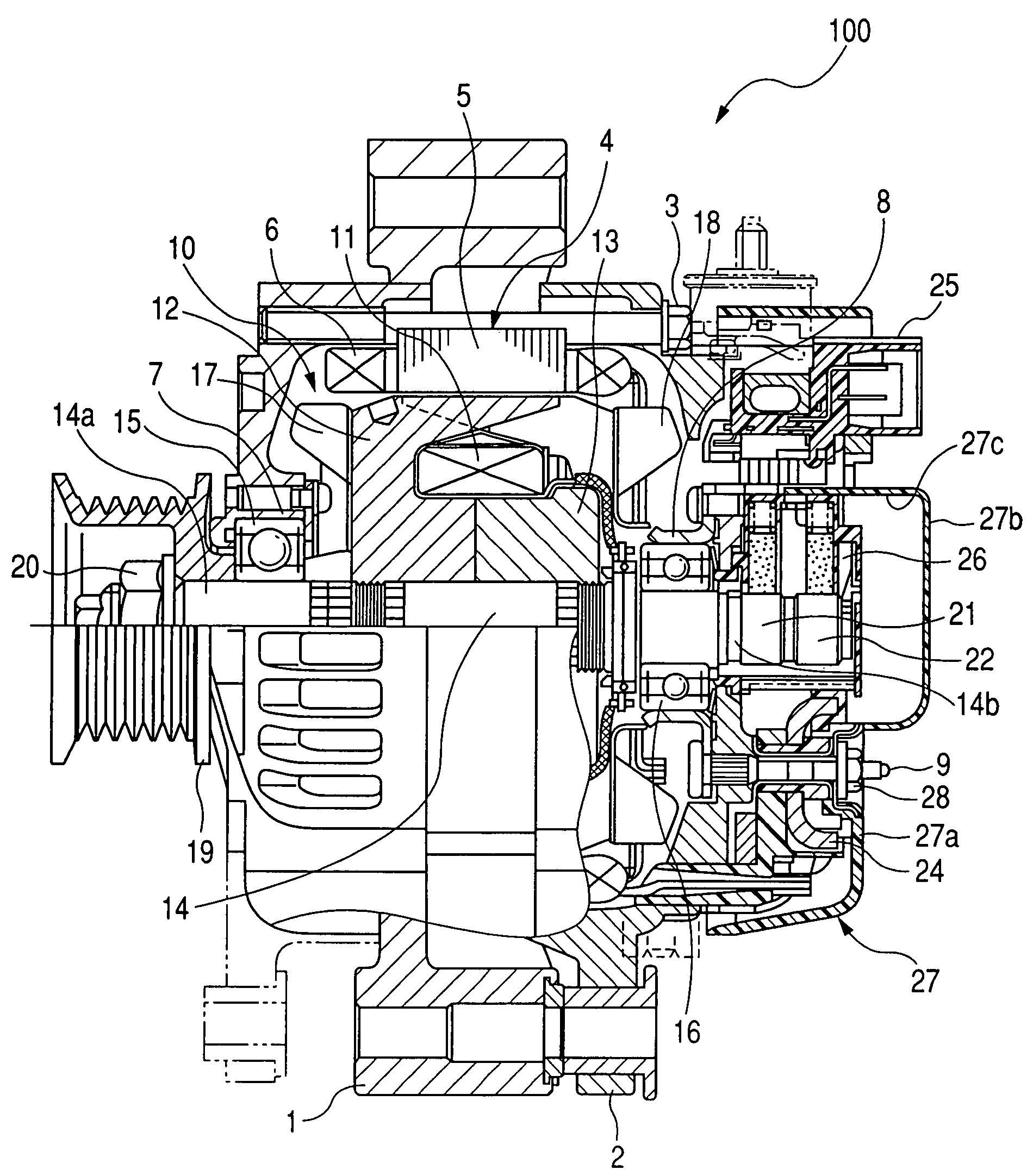
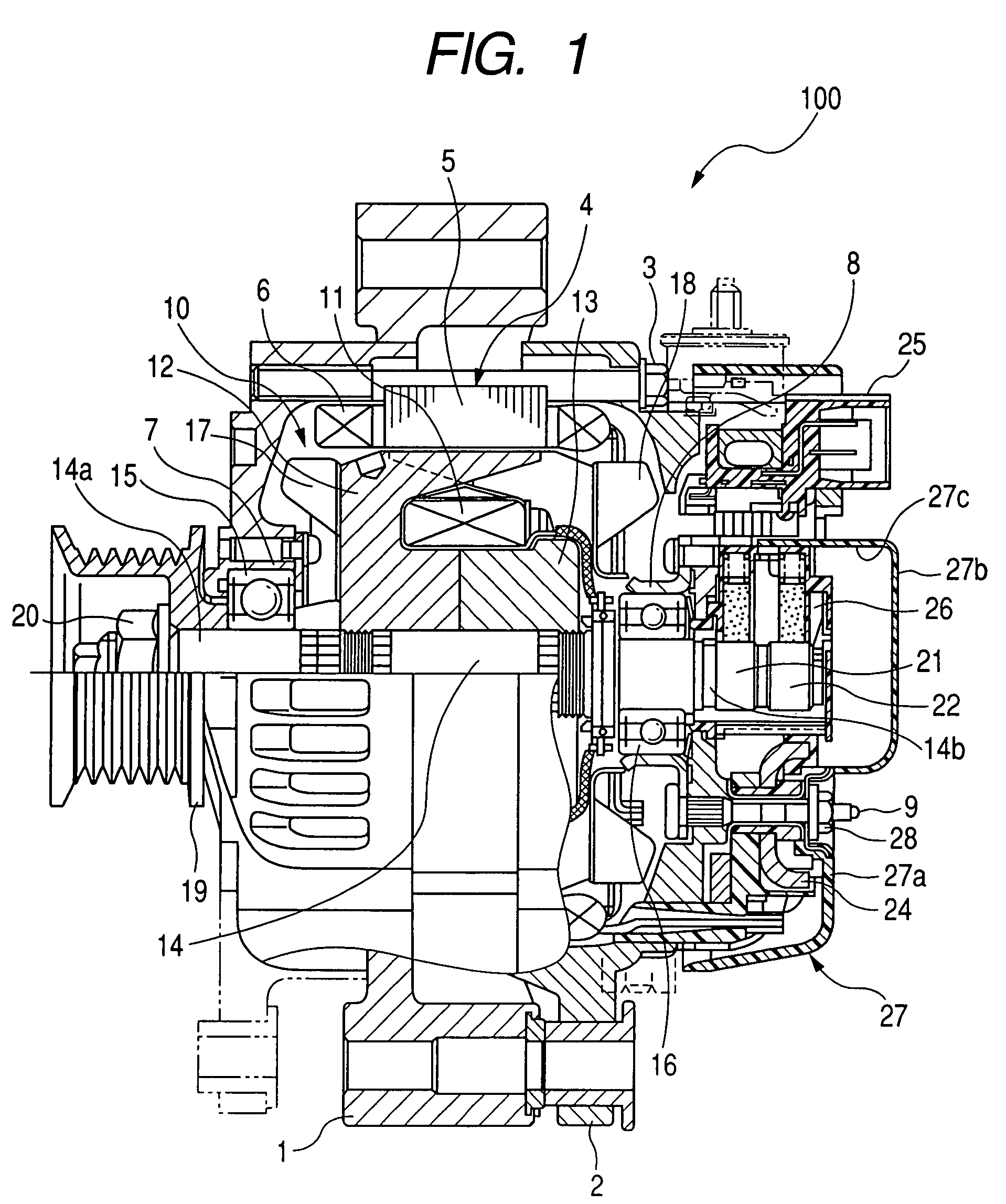
[0024]FIG. 1 is a longitudinal cross sectional view showing an overall structure of the vehicle alternator of the present embodiment implementing the present invention.

[0025]As shown in FIG. 1, the vehicle alternator 100 includes a front frame 1, a rear frame 2, a stator 4 supported with the front and rear frames 1, 2, a rotor 10 carried on a rotary shaft 14 to be rotatable inside th...


PUM


Abstract

A vehicle alternator is disclosed as having a stator having a stator winding, a rotor carried on a rotary shaft and rotatably supported inside an inner periphery of the stator, an electric device involving a rectifier for converting an AC voltage, induced in the stator winding, into a DC voltage, and a protector cover for covering the electric device. The protector cover includes a cover body, placed in a position to cover the electric device involving the rectifier, and a cover convex portion extending outward from the cover body along an axis of the rotary shaft of the rotor. The cover convex portion has an inside formed with an open space in which no electric device is disposed.

Description

CROSS REFERENCE TO RELATED APPLICATIONS[0001]This application is related to Japanese Patent Application No. 2006-228381, filed on Aug. 24, 2006, the content of which is hereby incorporated by reference.BACKGROUND OF THE INVENTION[0002]1. Technical Field of the Invention[0003]The present invention relates to vehicle alternators and, more particularly, to a vehicle alternator installed on a vehicle such as a passenger car and a truck or the like.[0004]2. Description of the Related Art[0005]With vehicle alternators of the related art, it has been a general practice for electric devices such as a regulator and a rectifier, etc., to be located on a body of the alternator in an area remotest from a pulley (see, for instance, U.S. Pat. No. 6,710,499). The alternator usually includes a protector cover in the form of a protector cover that is fixed to the body of the alternator to cover the electric devices. The protector cover takes the form of a structure configured to prevent foreign matt...

Claims


Application Information

Patent Timeline
Patent Type & Authority Patents(United States)
IPC IPC(8): H02K5/00
CPCH01R39/388H02K5/04H02K5/10H02K5/141H02K11/046H02K19/365H02K11/05
Inventor TANAKA, AKIHIRO
Owner DENSO CORP
Learn More