Serrated MEMS resonators

a mems resonator and resonator technology, applied in piezoelectric/electrostrictive/magnetostrictive devices, electrostatic generators/motors, oscillators, etc., can solve the problem of upper limit of the useful range of drive voltage amplitude, undesirable shift in the resonant frequency of the system, and the configuration of the actuator is not suitable for use. problem, to achieve the effect of reducing the amplitude, compromising the performance of the system problem

Active Publication Date: 2009-06-09
SITIME
View PDF5 Cites 18 Cited by
  • Summary
  • Abstract
  • Description
  • Claims
  • Application Information

AI Technical Summary

Benefits of technology

[0009]One advantage of the disclosed system is that such a configuration permits higher amplitude signals to be applied to the drive electrode without the performance of the system being compromised by nonlinear effects. In addition, the serrated electrode configuration enables a sufficiently high actuating force to be maintained even though the distance traversed by the MEMS resonator arm during operation is quite small. Further, the serrated electrode configuration allows a MEMS resonator system to withstand larger fluctuations in voltage and larger substrate stresses without experiencing a substantial shift in resonant frequency.

Problems solved by technology

However, such an actuator configuration has certain drawbacks.
Thus, there is an upper limit on the useful range of drive voltage amplitudes that parallel plate actuators can accommodate.
Each of these phenomena can change the electrostatic spring properties of the resonator system, resulting in an undesirable shift in the resonant frequency of the system.
However, prismatic comb geometries generally result in reduced actuating force relative to parallel-plate geometry of equivalent size, meaning that prismatic comb actuators require higher voltage to achieve the same performance, making prismatic comb actuators undesirable for low-power MEMS applications.
Since MEMS structures usually are not purely translational, the rigid translational structure of a typical triangular comb actuator is generally unsuitable for many MEMS implementations.

Method used


Image

  • Serrated MEMS resonators
  • Serrated MEMS resonators
  • Serrated MEMS resonators

Examples


Embodiment Construction

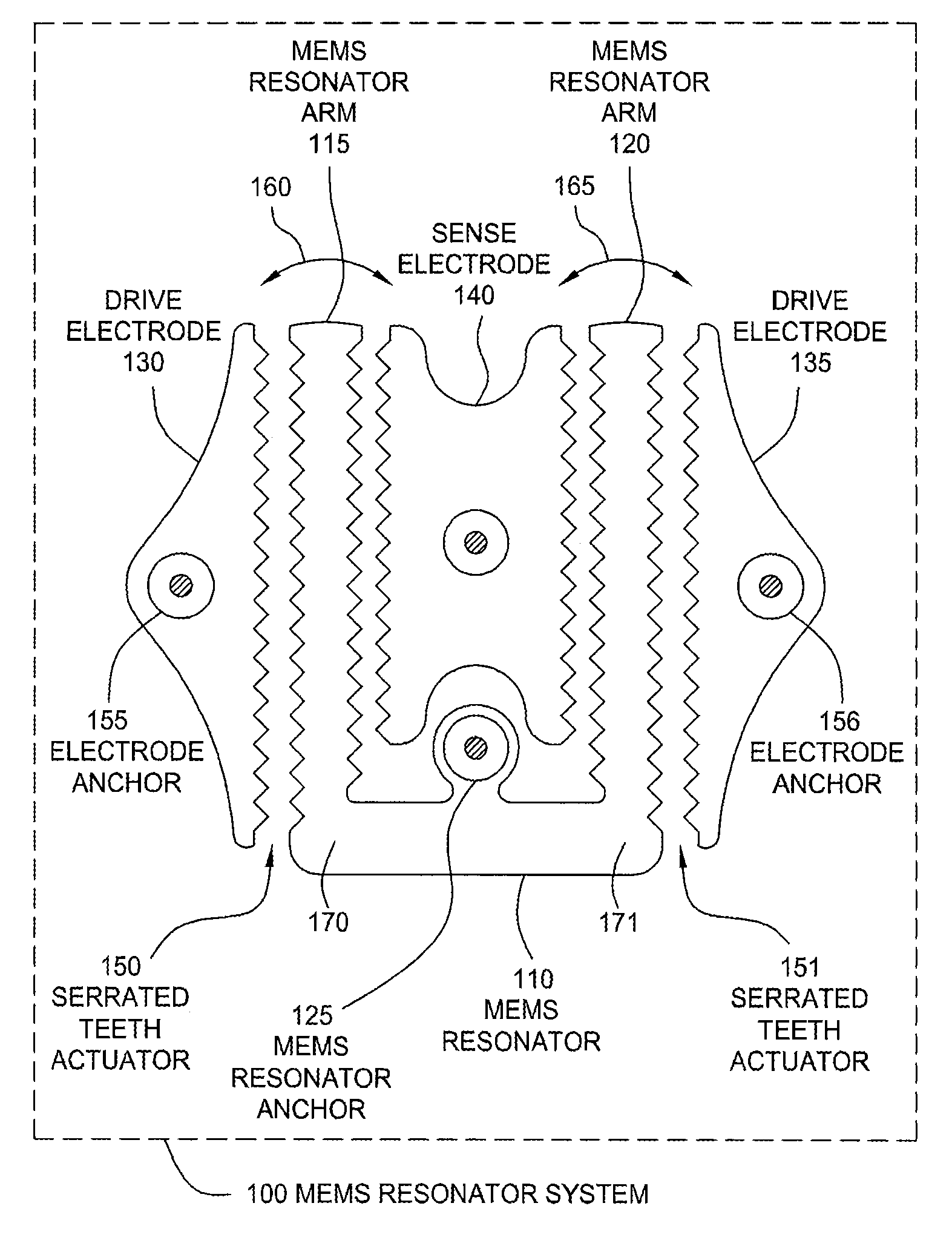
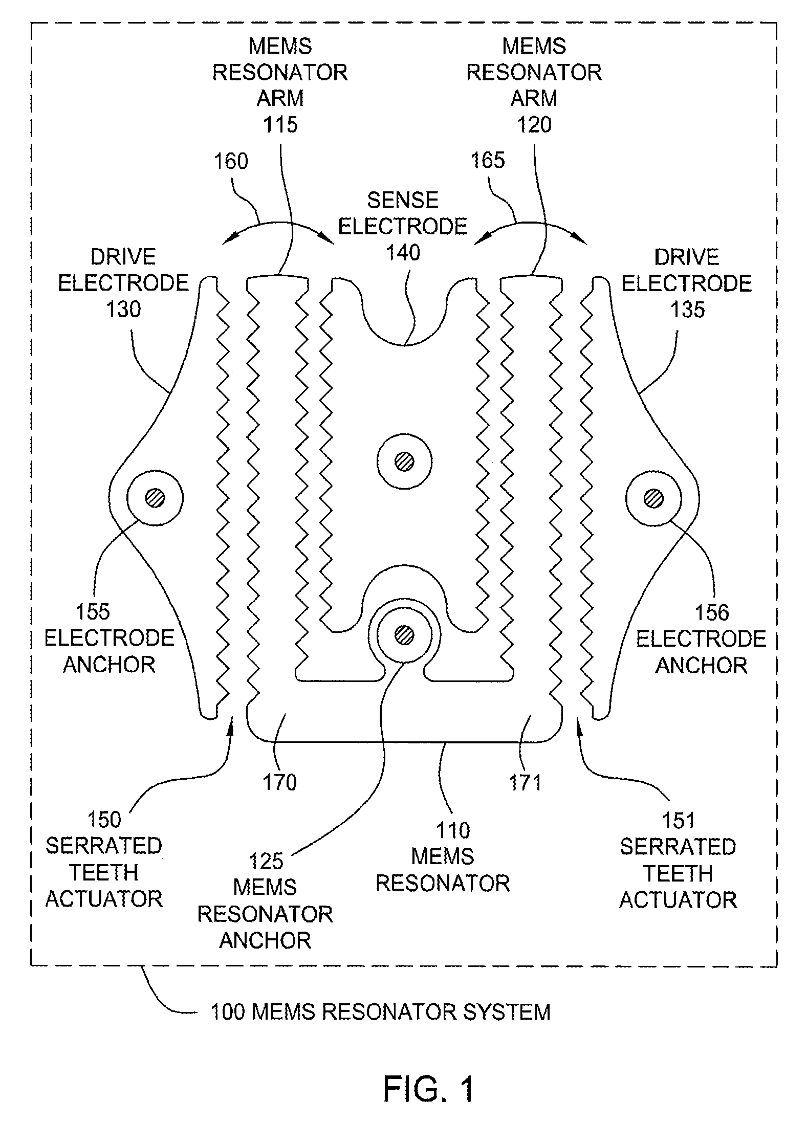
[0017]FIG. 1 is a conceptual diagram of a MEMS resonator system 100, according to one embodiment of the present invention. As shown, the MEMS resonator system 100 includes, without limitation, a MEMS resonator 110, drive electrodes 130 and 135, and a sense electrode 140. The MEMS resonator 110 includes MEMS resonator arms 115 and 120 that are mechanically coupled. As previously described herein, by applying a time-varying signal to drive electrodes 130 and 135 at a given frequency and, optionally, a DC voltage between the MEMS resonator 110 and drive electrodes 130 and 135, electrostatic forces are generated that cause the MEMS resonator arms 115 and 120 to oscillate in a tuning fork fashion, as indicated by arrows 160 and 165, respectively. In response to the motion of the MEMS resonator arms 115 and 120, the average capacitance between the sense electrode 140 and the MEMS resonator arms 115 and 120 changes at a substantially constant frequency. Thus, the capacitance can be measure...


PUM


Abstract

One embodiment of the present invention sets forth a serrated tooth actuator for driving MEMS resonator structures. The actuator includes a fixed drive electrode having a serrated tooth surface opposing a MEMS resonator arm also having a serrated tooth surface, where the MEMS resonator arm is configured to rotate towards the drive electrode when an AC signal is applied to the drive electrode. Such a configuration permits higher amplitude signals to be applied to the drive electrode without the performance of the actuator being compromised by nonlinear effects. In addition, the serrated tooth configuration enables a sufficiently high actuating force to be maintained even though the distance traversed by the MEMS resonator arm during operation is quite small. Further, the serrated configuration allows a MEMS resonator system to withstand larger fluctuations in voltage and larger substrate stresses without experiencing a substantial shift in resonant frequency.

Description

BACKGROUND OF THE INVENTION[0001]1. Field of the Invention[0002]Embodiments of the present invention generally relate to microelectromechanical systems and, more specifically, to serrated MEMS resonators.[0003]2. Description of the Related Art[0004]Microelectromechanical system (MEMS) devices are currently being developed for a wide variety of applications. One example of such a device is a MEMS resonator, which can be used in the timing circuitry of electronic devices. MEMS resonator systems typically include multiple electrodes to drive the MEMS resonator. As is well-known, when a bias is applied to a drive electrode, a charge builds up on the electrode that generates an electrostatic force between the electrode and an opposite charge built up on the MEMS resonator. By applying a time-varying voltage signal to the drive electrode, often in combination with a DC voltage, a time-varying electrostatic force can be generated that causes the MEMS resonator to oscillate. Since the elect...

Claims


Application Information

Patent Timeline
Patent Type & Authority Patents(United States)
IPC IPC(8): H03H9/125H03B5/30H03H9/24H03H9/46
CPCH03H9/02244H03H9/02259H03H9/02433H03H9/2405H03H9/2484H03H2009/0248H03H2009/02496
Inventor HAGELIN, PAUL MERRITTPEDERSEN, DAVID RAYMOND
Owner SITIME
Why Eureka
Try Eureka