Laser radar apparatus that measures direction and distance of an object

a laser radar and distance measurement technology, applied in the direction of distance measurement, mirrors, instruments, etc., can solve the problems of large loss of beam splitting efficiency, inability to prevent diffusion of outgoing light, and downsizing of the apparatus, so as to improve the accuracy of detecting direction, improve beam splitting efficiency, and sacrifice the small size of the laser radar apparatus

Inactive Publication Date: 2009-06-09
DENSO WAVE INC
View PDF8 Cites 12 Cited by
  • Summary
  • Abstract
  • Description
  • Claims
  • Application Information

AI Technical Summary

Benefits of technology

[0009]It is an object of the present invention to provide a laser radar apparatus that has an improved beam splitting efficiency and an improved accuracy of detecting the direction of an object and the distance to the object from the apparatus without sacrificing the small size of the laser radar apparatus due to the coaxial structure of the projection optical system and the photo detecting system.

Problems solved by technology

Hence, a large loss of the beam splitting efficiency is caused during the transmission and the reflection of the laser beam or the laser pulse through and from the optical isolator.
This conflicts with the tendency of downsizing of the apparatus.
Further, as in the case of the laser radar apparatus of Hoashi et al. or a laser radar apparatus of similar type where the outgoing light is deflected toward the measurement range by the concave mirror, a diffusion of the outgoing light can not be prevented after the outgoing light is deflected by the concave mirror due to the concaved-shape of the concave mirror.
In particular, if axis of the outgoing light emitted from the laser beam generating means is slightly deviated from the correct position or tilted from the correct direction before the outgoing light enters to the concave mirror, the situation will worsen due to the deflection by the concave mirror.
Thus, the laser radar apparatus of Hoashi et al. or a laser radar apparatus of similar type cannot ensure the accurate measurement of the distance of the object, in particular an object located far from the apparatus.

Method used


Image

  • Laser radar apparatus that measures direction and distance of an object
  • Laser radar apparatus that measures direction and distance of an object
  • Laser radar apparatus that measures direction and distance of an object

Examples


first embodiment

[0031]Referring to FIGS. 1-7, a laser radar apparatus according to a first embodiment of the present invention will be described.

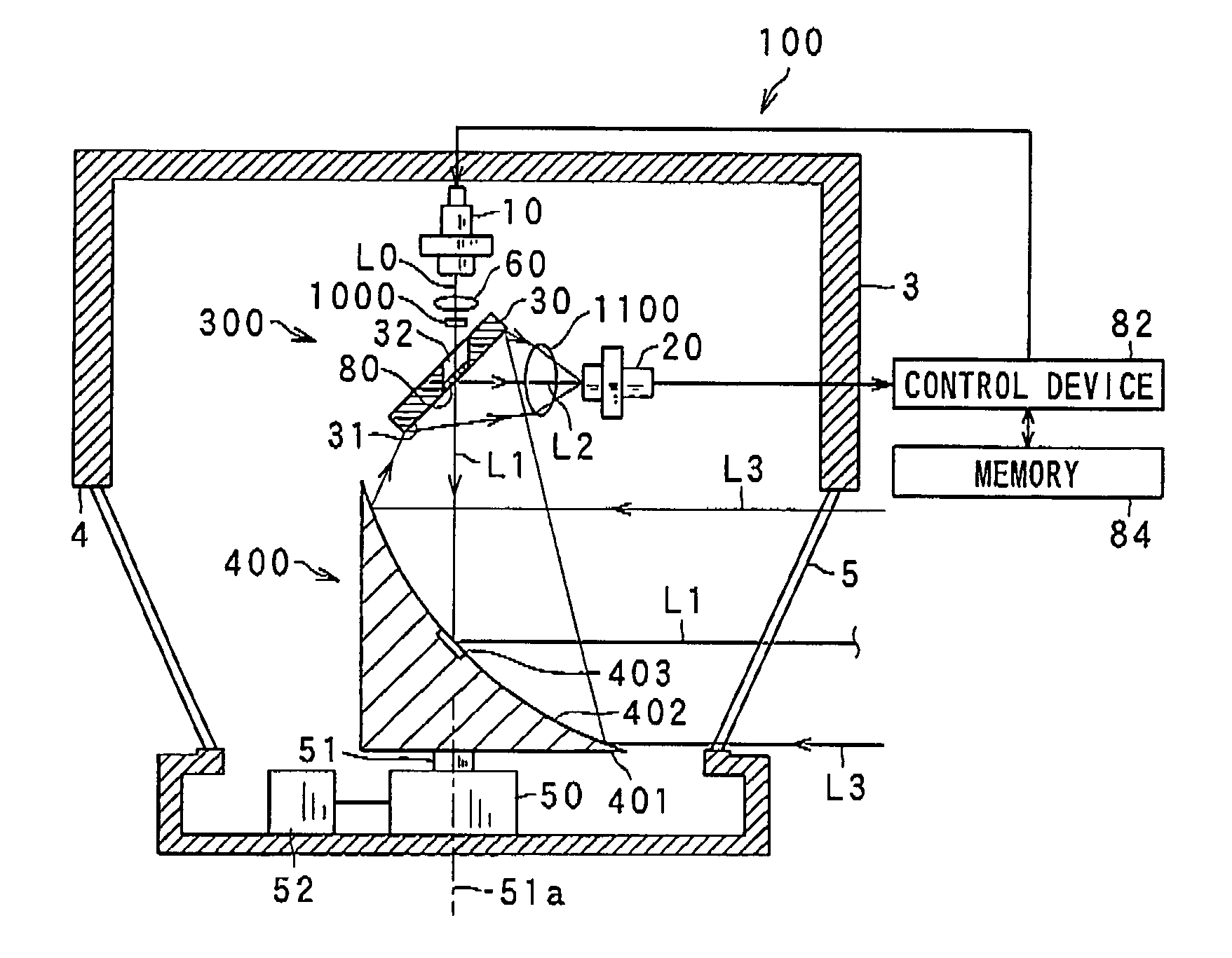
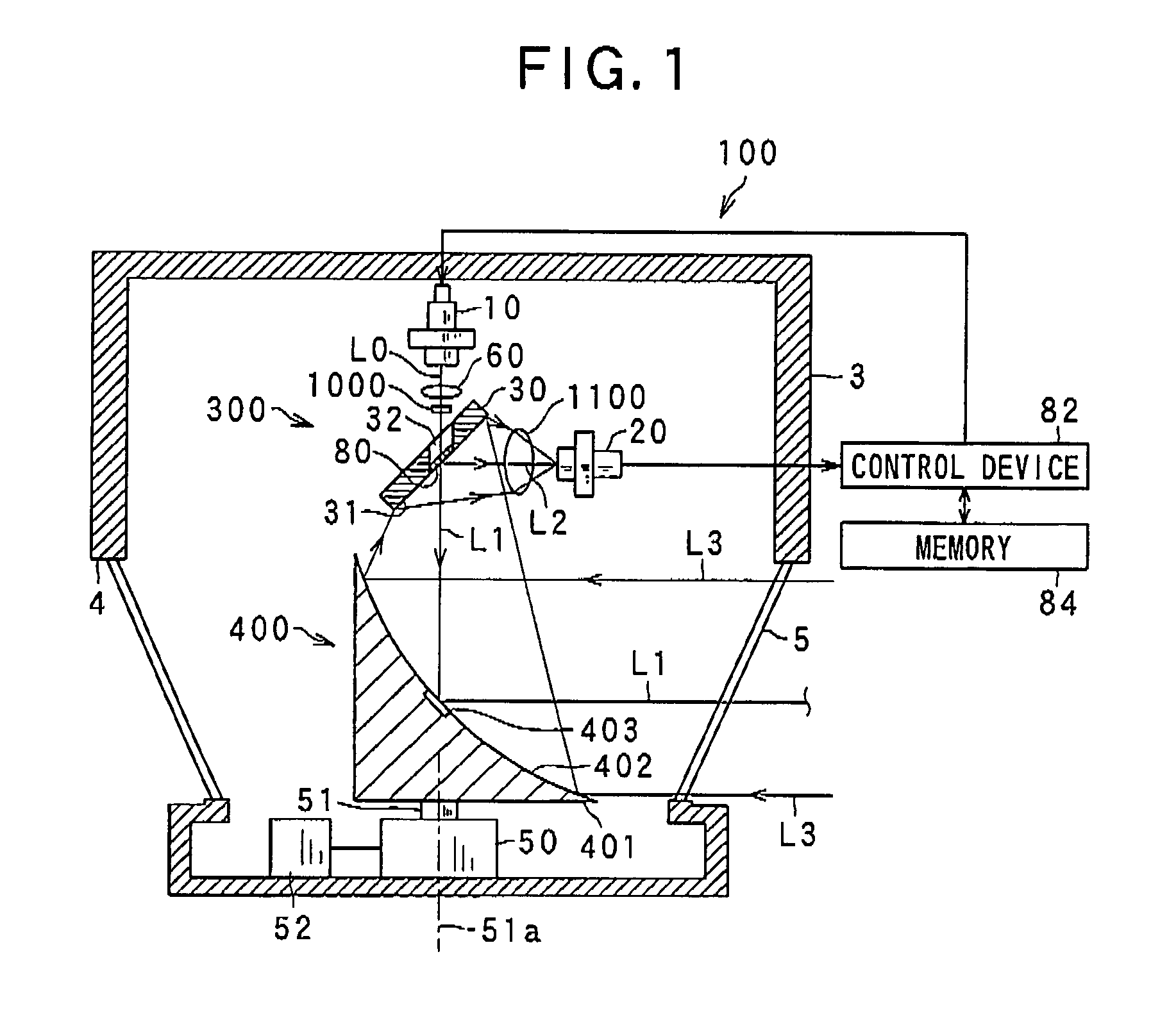
[0032]FIG. 1 is a schematic view of the laser radar apparatus 100 according to the first embodiment of the present invention.

[0033]As shown in FIG. 1, the laser radar apparatus 100 including a laser diode 10 and a photo diode 20 is designed to detect the direction to an object located in a measurement range, if it exists, and the distance of the object from the apparatus based on the difference of the phases of an outgoing light L0 emitted by the laser diode 10 and an incoming light L3 that is reflected back by the object and received by the photo diode 20, or the time of flight between the emission of an outgoing light L0 and reception of an incoming light L3 utilizing the speed of light. In this embodiment, the laser diode 10 emits a laser pulse.

[0034]The laser diode 10 emits a laser pulse having an axis thereof as an outgoing laser beam L0 into a measur...

second embodiment

[0113]Referring to FIGS. 9-11, a laser radar apparatus according to a second embodiment of the present invention will be described.

[0114]FIG. 9 is a schematic view of the laser radar apparatus 100B according to the second embodiment of the present invention.

[0115]In the present embodiment, the differences from the previous embodiment are based on the absence of the optical element 1000 between the laser diode 10 and the mirror 30 and the use of a rotating device 400A having a concave mirror 410. Thus, detailed discussion about the constituents of the laser radar apparatuses having the same function and the structure with those used in previous embodiments will be omitted.

[0116]As in the case of the first embodiment, the laser radar apparatus 100B is designed to detect the direction and the distance from the apparatus to an object based on the difference of the phases of outgoing light emitted by the laser diode 10 via the half-silvered mirror 80 and a flat mirror surface 411a, and i...

third embodiment

[0138]Referring to FIGS. 12-13, a laser radar apparatus according to a third embodiment of the present invention will be described.

[0139]FIG. 12 is a schematic view of the laser radar apparatus 100C according to the third embodiment of the present invention.

[0140]In the present embodiment, the differences from the second embodiment are based on the different structure of a rotary device 400B from the rotary device 400B because the rotary device 400B includes a concave mirror 420 that is different from the concave mirror 410. Thus, the detailed discussion about the constituents of the laser radar apparatuses having the same function and the structure with those used in the previous embodiments will be omitted.

[0141]The laser radar apparatus 100C has a rotary device 400B having a concave mirror 420. The concave mirror 420 has a concave reflecting portion 402 that has the concave-shaped mirror surface 402a and a flat reflecting portion 421 that has a flat mirror surface 421a. The refle...


PUM


Abstract

There is provided a laser radar apparatus including laser beam generating means, photo detecting means, a mirror assembly, light deflecting means, and rotation driving means. The laser beam generating means emits a laser beam having an axis thereof. The photo detecting means detects a reflected laser beam that is reflected back by an object. The mirror assembly includes a through-hole that transmits the laser beam and a reflecting surface that reflects a reflected laser beam reflected back by the object toward the photo detecting means. The light deflecting means has a flat mirror surface and a concave-shaped mirror surface, and reflects the laser beam toward a measurement range and deflects the reflected laser beam from the object toward the mirror assembly. The rotation driving means rotates the light deflecting means so as to direct the laser beam toward the measurement range.

Description

CROSS REFERENCE TO RELATED APPLICATION[0001]The present application relates to and incorporated by reference Japanese Patent Applications 2007-293224 filed on Nov. 12, 2007.BACKGROUND OF THE INVENTION[0002]1. The Field of the Invention[0003]The invention relates to a laser radar apparatus capable of measuring both the direction of an object and the distance to an object from the apparatus using laser beam.[0004]2. Description of the Prior Art[0005]As laser radar apparatus capable of measuring both the direction of an object and the distance to an object from the apparatus, there is a known apparatus such as disclosed by Hoashi et al. in Japanese Patent No. 2789741.[0006]The laser radar apparatus of Hoashi et al. includes a laser beam generating means for emitting a laser beam or a laser pulse serving as an outgoing light into a measurement range, the outgoing light having an optical axis thereof, a photo detecting means for detecting the reflected laser beam or the reflected laser p...

Claims


Application Information

Patent Timeline
Patent Type & Authority Patents(United States)
IPC IPC(8): G01C3/08
CPCG01S7/4812G01S7/4813G01S7/484G02B5/08G02B26/105G02B27/1093G02B27/143G02B27/144
Inventor OKADA, MASANORIKONOSU, KOJITANAKA, HIDEYUKI
Owner DENSO WAVE INC
Why Eureka
Try Eureka