Automotive dynamoelectric machine

a dynamoelectric machine and motor technology, applied in the direction of magnetic circuit rotating parts, electrical apparatus construction details, shape/form/construction, etc., can solve the problem of limiting the improvement of heat radiating characteristics, and achieve the improvement of heat radiating performance, excessive temperature increase, and increased heat radiating area and heat transfer rate.

Active Publication Date: 2009-06-09
MITSUBISHI ELECTRIC CORP
View PDF21 Cites 3 Cited by
  • Summary
  • Abstract
  • Description
  • Claims
  • Application Information

AI Technical Summary

Benefits of technology

[0010]The present invention aims to solve the above problems and an object of the present invention is to provide a compact automotive dynamoelectric machine that has superior cooling characteristics by forming ventilating apertures that have a circular cross section on a heatsink instead of thin plate-shaped fins to improve heat radiating performance of the heatsink.
[0012]According to the present invention, because a large number of ventilating apertures that have a circular cross section are disposed through the heatsink so as to have aperture directions that are parallel to each other, heat radiating area and heat transfer rate can be increased compared to thin plate-shaped fins, improving heat radiating performance. Thus, excessive temperature increases can be suppressed in a rectifier and a regulator, enabling stable operation of the dynamoelectric machine to be achieved. In addition, because heat radiating characteristics per unit area are improved, the heatsink can be reduced in size, enabling reductions in the size of the dynamoelectric machine to be achieved.

Problems solved by technology

However, because the heatsink is formed by arraying a large number of thin plate-shaped fins on the rear surface of the base surface, there has been a limit to improving heat radiating characteristics due to constraints on machining the fins.

Method used


Image

  • Automotive dynamoelectric machine
  • Automotive dynamoelectric machine
  • Automotive dynamoelectric machine

Examples


embodiment 1

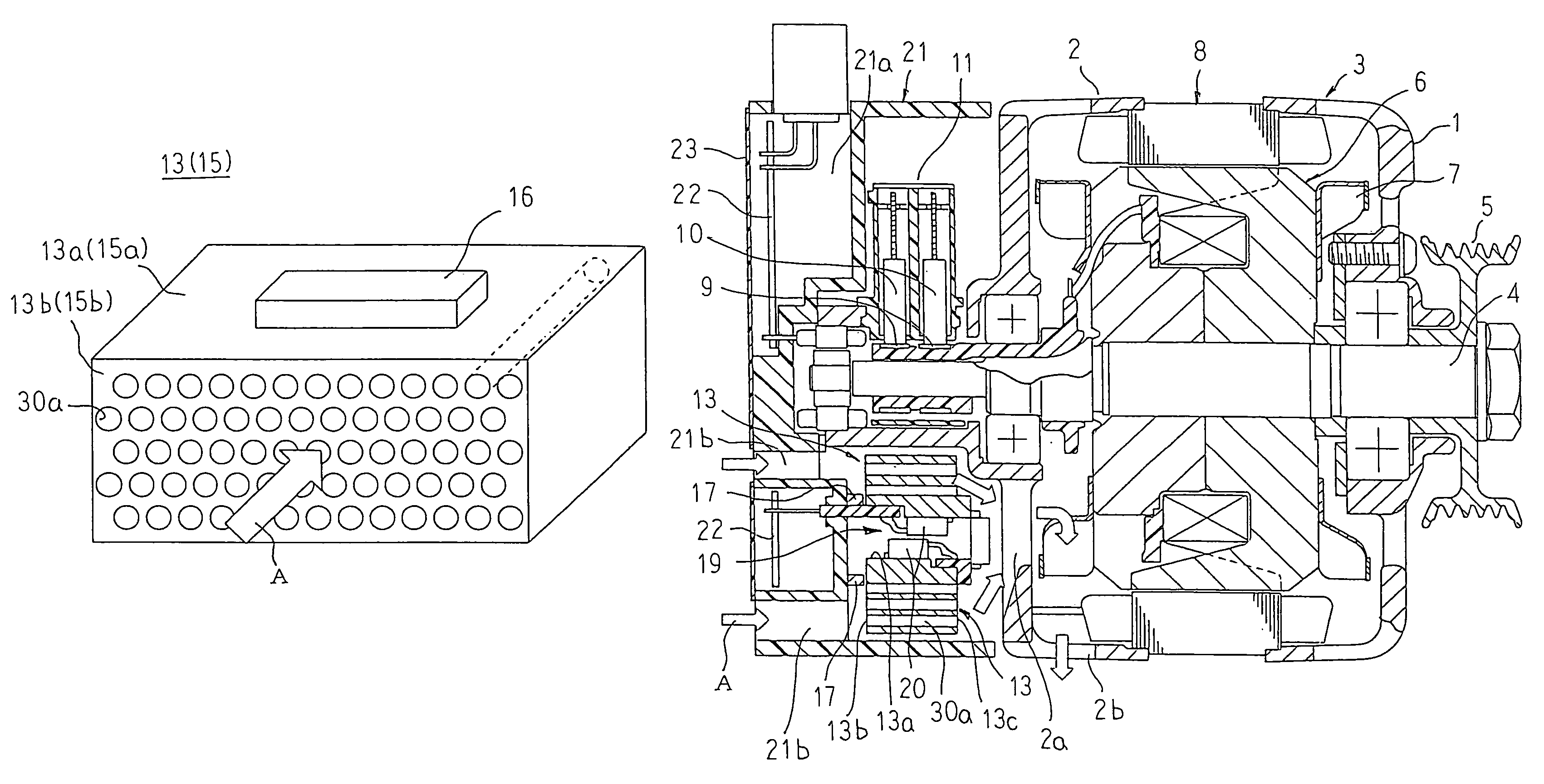
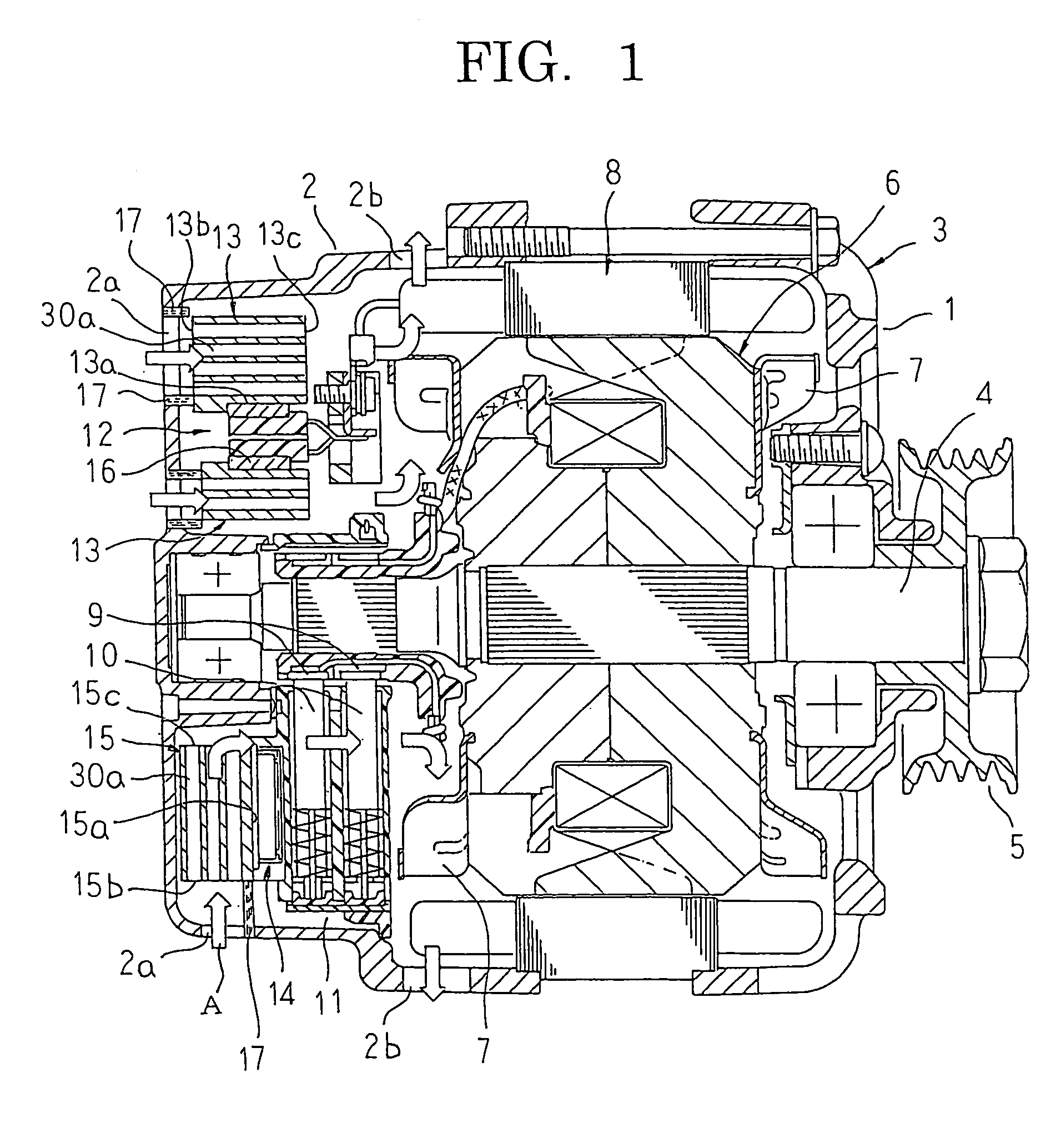
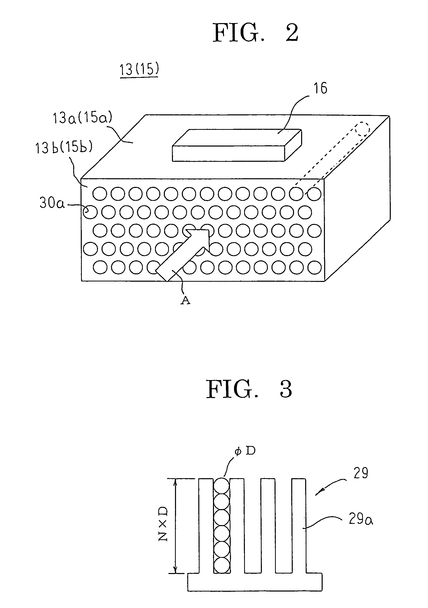
[0024]FIG. 1 is a longitudinal section of an automotive alternator according to Embodiment 1 of the present invention, FIG. 2 is a perspective that explains a configuration of a heatsink in the automotive alternator according to Embodiment 1 of the present invention, and FIG. 3 is a diagram that explains heat radiating characteristics of the heatsink in the automotive alternator according to Embodiment 1 of the present invention. Moreover, in FIG. 1, arrows A represent cooling airflows.

[0025]In FIG. 1, an automotive alternator includes: a case 3 that is constituted by a front bracket 1 and a rear bracket 2 that are each approximately bowl-shaped and made of aluminum; a shaft 4 that is rotatably supported by the case 3; a pulley 5 that is fixed to an end portion of the shaft 4 that projects outward at a front end of the case 3; a rotor 6 that is fixed to the shaft 4 and accommodated inside the case 3; fans 7 that are fixed to two axial end surfaces of the rotor 6; a stator 8 that is ...

embodiment 2

[0043]FIG. 4 is an end elevation of a heatsink in an automotive alternator according to Embodiment 2 of the present invention viewed from an apertured surface side.

[0044]In FIG. 4, semiconductor elements 16 are mounted to four surfaces, excluding an air intake apertured surface 13b and an air discharge apertured surface 13c, of a heatsink 13 that is formed into a rectangular parallelepiped.

[0045]Moreover, the rest of this embodiment is configured in a similar manner to Embodiment 1 above.

[0046]A large number of ventilating apertures 30a are formed so as to have aperture directions that are parallel to the element mount surfaces 13a and parallel to each other so as to pass through from an air intake apertured surface 13b to an air discharge apertured surface 13c that face each other on mutually opposite sides of the element mount surfaces 13a of the heatsink 13. These ventilating apertures 30a are arrayed in a staggered pattern within a cross section that is perpendicular to the aper...

embodiment 3

[0051]FIG. 5 is an end elevation of a heatsink in an automotive alternator according to Embodiment 3 of the present invention viewed from an apertured surface side.

[0052]In FIG. 5, a large number of ventilating apertures 30b that have a circular cross section are formed in a heatsink 13A so as to have aperture directions that are parallel to an element mount surface 13a and parallel to each other so as to pass through from an air intake apertured surface 13b to an air discharge apertured surface that face each other on mutually opposite sides of the element mount surface 13a. These ventilating apertures 30b are formed so as to have diameters that increase as distance from the element mount surface 13a increases. In addition, distances between adjacent ventilating apertures 30b are adjusted such that the percentage of area occupied by the ventilating apertures 30b in a cross section that is perpendicular to the aperture directions, i.e., the porosity, is constant over the entire surf...


PUM


Abstract

A large number of ventilating apertures that have a circular cross section are disposed through the heatsink so as to extend from an air intake apertured surface to an air discharge apertured surface so as to have aperture directions that are parallel to each other and parallel to an element mount surface, and the heatsink is disposed such that the air intake apertured surface faces an air intake aperture and the aperture directions of the ventilating apertures are aligned in a direction of flow of a cooling airflow.

Description

BACKGROUND OF THE INVENTION[0001]1. Field of the Invention[0002]The present invention relates to an automotive dynamoelectric machine that is mounted to a vehicle engine, and particularly relates to a construction of a heatsink that is mounted to a heat-generating element and that effectively radiates heat that is generated by the heat-generating element.[0003]2. Description of the Related Art[0004]Conventional automotive dynamoelectric machines include: a case that is constituted by a front bracket and a rear bracket that are made of aluminum; a shaft that is rotatably disposed in the case by means of bearings; a rotor that is fixed to the shaft and accommodated inside the case; fans that are fixed to two end surfaces of the rotor; a stator that is fixed to an inner wall surface of the case so as to surround the rotor; slip rings that are fixed to a rear end of the shaft and that supply electric current to the rotor; a pair of brushes that are disposed inside the case so as to that...

Claims


Application Information

Patent Timeline
Patent Type & Authority Patents(United States)
IPC IPC(8): H05K7/20
CPCH02K5/20H02K9/06H02K11/048H02K5/207H02K11/05
Inventor UEHARA, NOBUAKIOGUSHI, TETSUROASAO, YOSHIHITOISODA, HITOSHI
Owner MITSUBISHI ELECTRIC CORP
Why Eureka
Try Eureka