Storage tank for a cryogenic liquid and method of re-filling same

a cryogenic liquid and storage tank technology, applied in the direction of liquid handling, container discharging methods, container filling under pressure, etc., can solve the problems of raising the vapor pressure in the cryogenic space, the fill line is unsuitable for use as a vent line, and the incoming cryogenic liquid is not as effective at condensing vapor, etc., to reduce the number of heat transfer paths, reduce heat leakage, and reduce the complexity of the piping arrangemen

Active Publication Date: 2009-06-16
OLYMPUS CORP +1
View PDF19 Cites 20 Cited by
  • Summary
  • Abstract
  • Description
  • Claims
  • Application Information

AI Technical Summary

Benefits of technology

[0010]The receptacle preferably comprises a shut off valve with a valve member that is biased against a seat. Cryogenic liquid can not flow through the receptacle when the valve member is in contact with the seat. The valve member is mechanically moved away from the seat when a re-filling nozzle is attached to the receptacle. This is an additional safety feature for stopping cryogenic liquid from leaking from the receptacle when the re-filling nozzle is disconnected from it.
[0029]Accordingly, with the disclosed storage tank for a cryogenic liquid and method it is possible to vent vapor from the cryogen space through a pipe that can also be employed to fill the cryogen space with a cryogenic liquid. This method allows venting the storage tank prior to re-filling, and using the vented vapor to pre-cool the fill line. The shared vent and fill line also reduces the number of heat transfer paths into the cryogen space, reducing heat leak. The integration of the fill line with the vent line can also result in a less complex piping arrangement, with less joints, resulting in less opportunity for leaks. This simplification of the piping arrangement over conventional designs also makes it possible to reduce manufacturing costs.

Problems solved by technology

Heat leak results in vaporization of cryogenic liquid, which in turn results in raising the vapor pressure in the cryogen space.
Consequently, with conventional storage tanks, this check valve makes the fill line unsuitable for use as a vent line.
A disadvantage of filling through such a pipe is that when filling the storage tank, the incoming cryogenic liquid is not as effective at condensing vapor that might be inside the cryogen space.

Method used


Image

  • Storage tank for a cryogenic liquid and method of re-filling same
  • Storage tank for a cryogenic liquid and method of re-filling same
  • Storage tank for a cryogenic liquid and method of re-filling same

Examples


Embodiment Construction

)

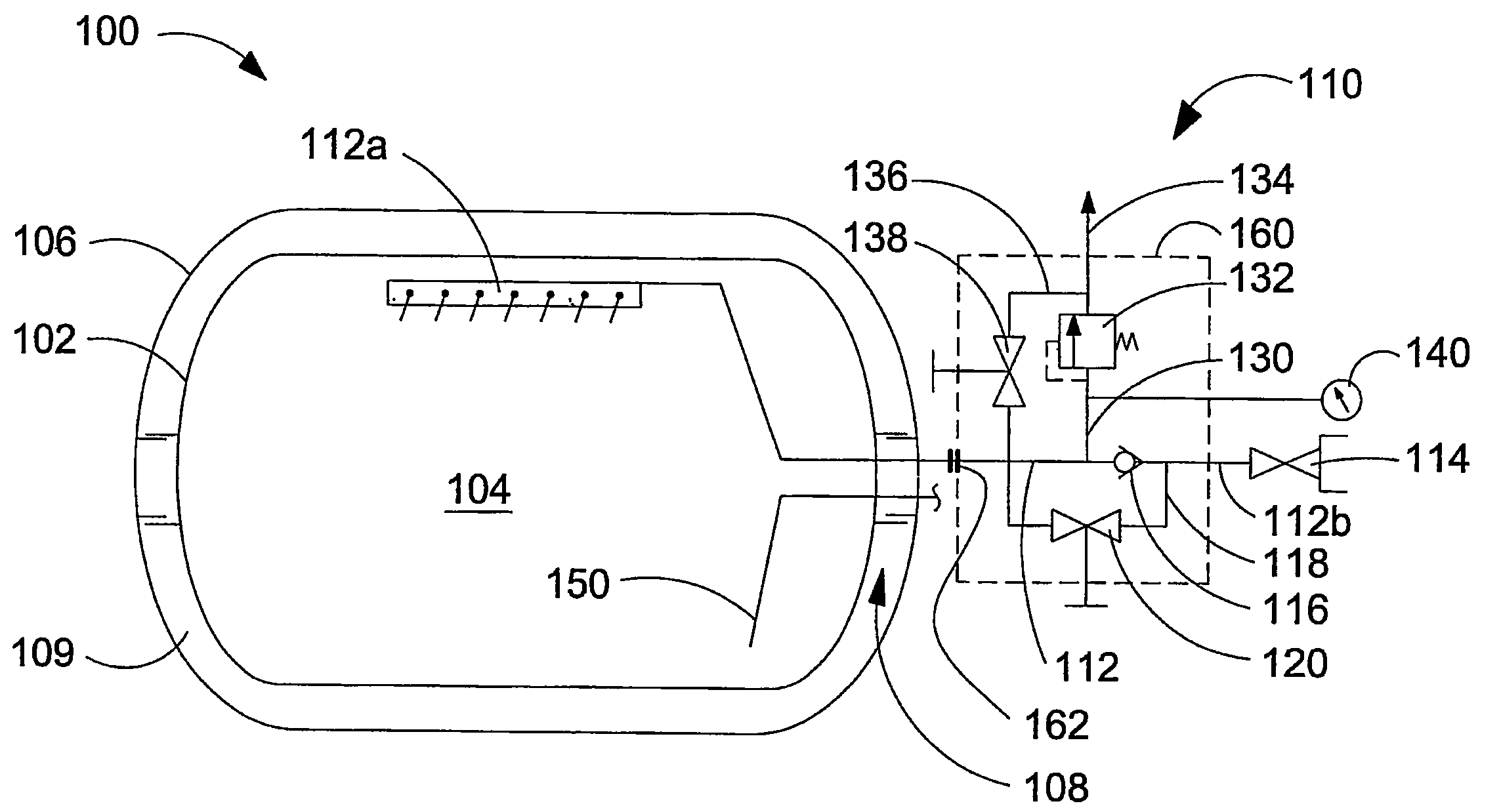
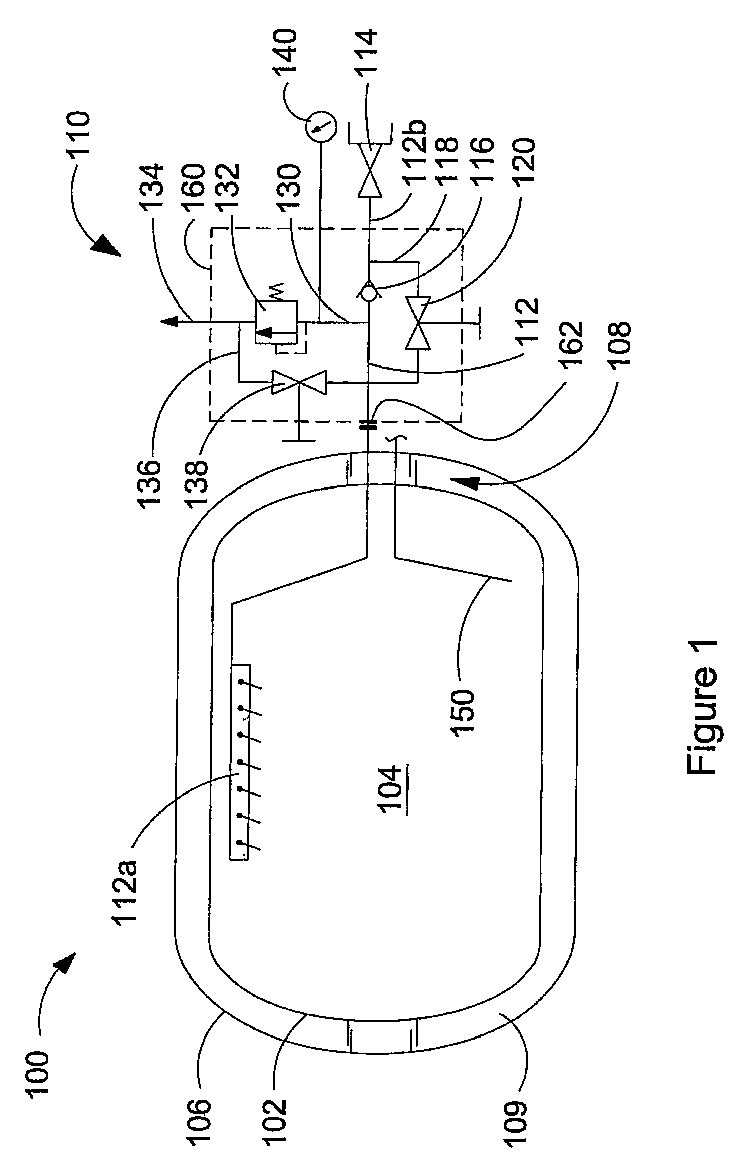
[0033]Referring to the schematic illustration of FIG. 1, storage tank 100 comprises inner vessel 102 defining cryogen space 104, outer shell 106 surrounding inner vessel 102, and support structure 108 for holding inner vessel 102 spaced apart from outer shell 106, whereby insulating space 109 is defined between inner vessel 102 and outer shell 106.

[0034]Combined fill and vent assembly 110 comprises conduit 112 having first end 112a with at least one opening disposed within an upper part of the cryogen space, and second end 112b outside of outer shell 106 and connected to receptacle 114. When a storage tank for cryogenic liquids is filled, normally a portion of the cryogen space is reserved for vapor. Filling cryogen space 104 completely with liquid would result in a very short holding time before vapor is vented from cryogen space 104 to relieve the vapor pressure. This is because even a small amount of heat leak into the cryogen space 104 would result in vaporization of some of th...


PUM


Abstract

A storage tank defines a cryogen space for storing a cryogenic liquid. The storage tank comprises a combined fill and vent assembly, which comprises a conduit having a first end with an opening disposed within an upper part of the cryogen space, and a second end outside of the cryogen space that is connected to a receptacle, to which a re-filling nozzle can be attached. A check valve disposed in the conduit allows flow only in the direction of filling the cryogen space with cryogenic liquid from the receptacle. A by-pass line is provided around the check valve with a valve disposed in the by-pass line that is operable to open or close to control flow through the by-pass line. The method comprises attaching a re-filling nozzle to the receptacle and opening the by-pass valve to vent vapor from the cryogen space to reduce vapor pressure therein and to cool the conduit, receptacle, re-filling nozzle, and fill line. After venting the storage tank, the by-pass valve is closed, and the storage tank can be re-filled through the receptacle and conduit.

Description

CROSS-REFERENCE TO RELATED APPLICATION(S)[0001]This application is a continuation of International Application No. PCT / CA2006 / 000898, having an international filing date of Jun. 1, 2006, entitled “Storage Tank for a Cryogenic Liquid and Method of Re-Filling Same”. International Application No. PCT / CA2006 / 000898 claimed priority benefits, in turn, from Canadian Patent Application No. 2,506,606 filed Jun. 3, 2005. International Application No. PCT / CA2006 / 000898 is hereby incorporated by reference herein in its entirety.FIELD OF THE INVENTION[0002]The present invention relates to a storage tank for a cryogenic liquid and a method of re-filling same. More particularly, the storage tank comprises an integrated apparatus for re-filling and venting the cryogen space.BACKGROUND OF THE INVENTION[0003]Cryogenic liquids are liquefied gases that generally have boiling points below −100° C. (about −150° F.) at atmospheric pressure. Examples of cryogenic liquids include liquid natural gas (LNG), ...

Claims


Application Information

Patent Timeline
Patent Type & Authority Patents(United States)
IPC IPC(8): F17C13/00F17C5/02F17C1/12F17C13/04
CPCF17C1/12F17C13/04F17C2201/0109F17C2201/035F17C2201/056F17C2203/03F17C2203/0619F17C2205/0329F17C2205/0332F17C2205/0335F17C2205/0385F17C2221/011F17C2221/012F17C2221/013F17C2221/014F17C2221/033F17C2223/0161F17C2223/033F17C2223/046F17C2225/044F17C2227/0107F17C2250/043F17C2250/0626F17C2250/0636F17C2260/021F17C2260/036F17C2270/0168Y02E60/321Y02E60/32
Inventor HARPER, GREGORYMARK, RANDALL
Owner OLYMPUS CORP
Why Eureka
Try Eureka