Animal containment transmitter system

a transmitter system and transmitter technology, applied in the field of signal transmitter systems, can solve the problems of inefficient production of unique electromagnetic signals and rapid movement of animals from fences, and achieve the effect of less heat and better matching the signal generator

Active Publication Date: 2009-06-16
RADIO SYST CORP
View PDF14 Cites 28 Cited by
  • Summary
  • Abstract
  • Description
  • Claims
  • Application Information

AI Technical Summary

Benefits of technology

[0010]An advantage of the present invention is that the transmitter system produces less heat than a conventional system.
[0011]Another advantage of the present invention is that an adjustable level of power is supplied to the signal generator to better match the signal generator to the attached impedance loop.

Problems solved by technology

The result is an electrical shock sufficiently unpleasant to cause the animal to move rapidly away from the fence before the next electrical impulse.
This leads to inefficient production of the unique electromagnetic signal.

Method used


Image

  • Animal containment transmitter system
  • Animal containment transmitter system
  • Animal containment transmitter system

Examples


Embodiment Construction

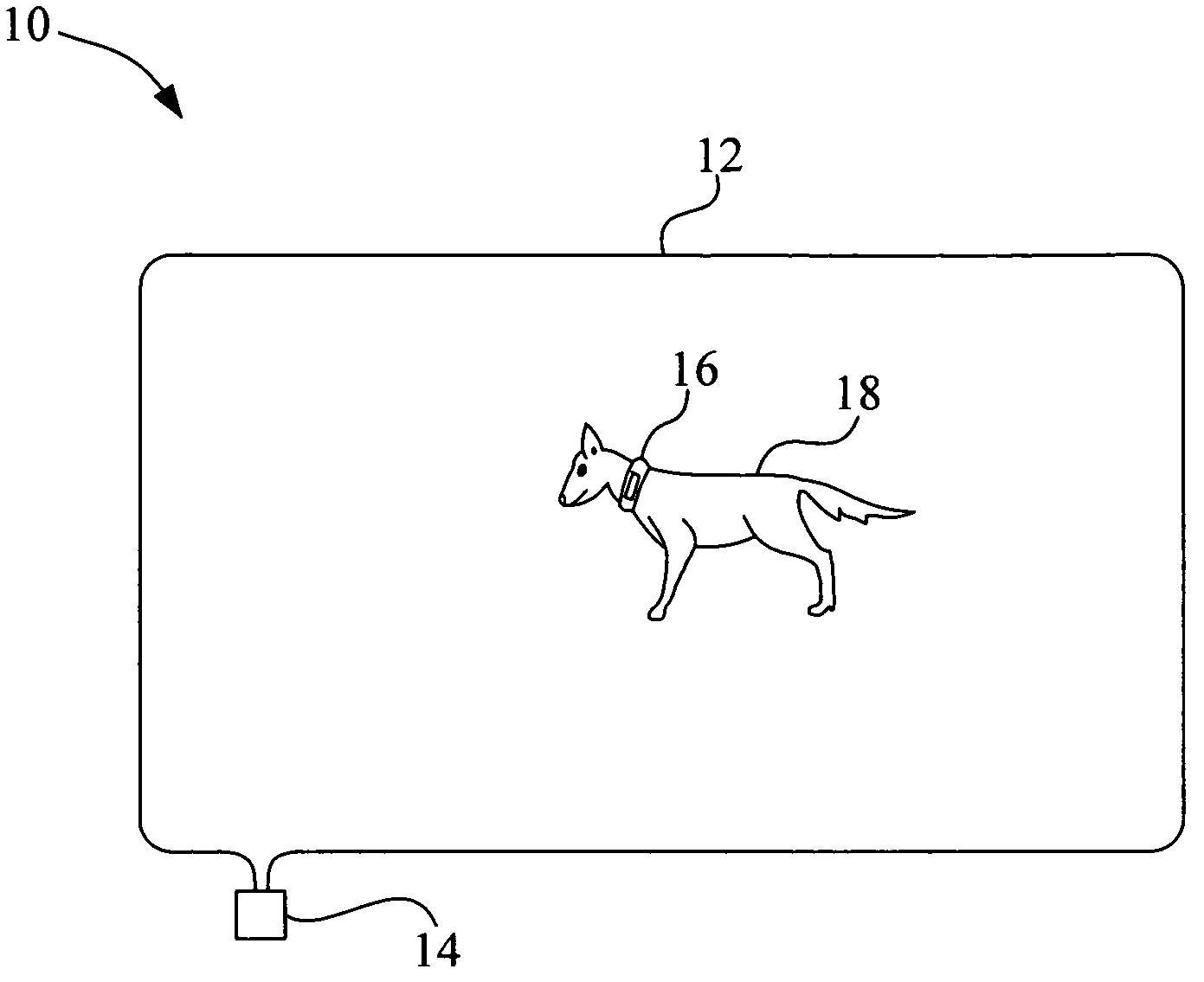
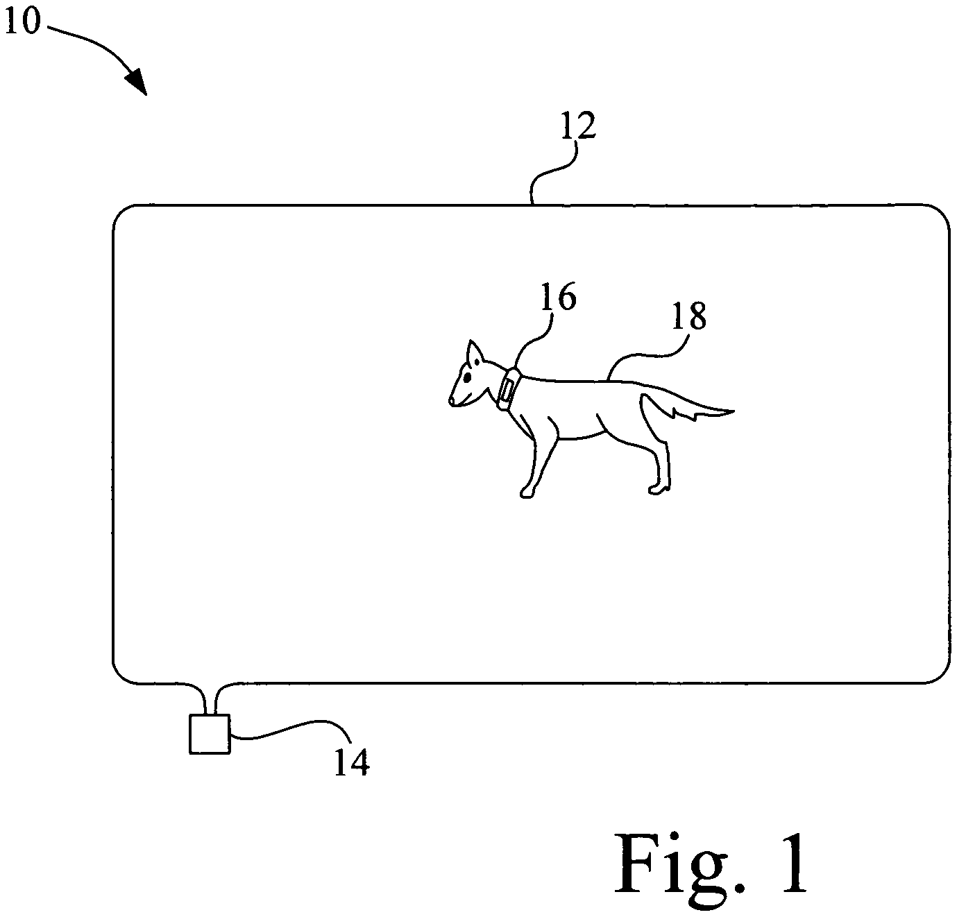
[0016]Referring now to the drawings, and more particularly to FIG. 1, there is shown a signal transmitter system 10 including an impedance loop 12 and a signal transmitter 14. Signal transmitter 14 interacts with receiver collar 16 that is positioned around the neck of dog 18. If dog 18 approaches a boundary defined by the location of impedance loop 12 a signal that is being transmitted over impedance loop 12 is detected by receiver collar 16 causing a corrective stimulus to be applied to dog 18, to thereby confine dog 18 in the area defined by the geometry of impedance loop 12. Signal transmitter 14 sends a unique current signal through impedance loop 12, which is hereinafter referred to as a current signal. It is known that a current signal sent through an inductive component creates a voltage signal as a result of the interaction of the current signal with the inductance of the inductive component, such as impedance loop 12.

[0017]Since impedance loop 12 can conceivably be any typ...


PUM


Abstract

A signal transmitter system for an animal training system including an electrical impedance loop, a signal generator and a power supply. The signal generator is connected to the electrical impedance loop. The signal generator provides a current signal to the electrical impedance loop. The power supply provides a voltage level to the signal generator. The voltage level is dependent upon a measured characteristic of a voltage signal that results from an interaction of the current signal with the electrical impedance loop.

Description

BACKGROUND OF THE INVENTION[0001]1. Field of the Invention[0002]The present invention relates to a signal transmitter system, and, more particularly, to a signal transmitter system for an animal containment system.[0003]2. Description of the Related Art[0004]Conventional and electrical fencing is commonly used to control the location of animals. Barrier fencing, which physically blocks the movement of the animal, is frequently used to confine both domestic pets and farm animals. Physical electrical fencing, which uses an electrical shock to discourage contact with the fence, is typically used to confine commercial livestock. The purpose of an electric fence is to keep farm animals within an area, or to prevent undesired animals from entering the property. High voltage electrical impulses are applied to the fence wire by an energizer. This impulse lasts only thousandths of a second but is repeated every second or so. An animal, which strays into contact with the wire, completes the c...

Claims


Application Information

Patent Timeline
Patent Type & Authority Patents(United States)
IPC IPC(8): A01K15/02
CPCA01K15/023
Inventor MOORE, WILLIAM P.
Owner RADIO SYST CORP
Why Eureka
Try Eureka