
Computer assisted knee arthroplasty instrumentation, systems, and processes

a computer-aided knee and arthroplasty technology, applied in the field of computer-aided knee arthroplasty instruments, systems, and processes, can solve the problems of changing the balance of the knee, increasing the risk of fat embolism and unnecessary blood loss in patients, and the wear and revision of knee implants, so as to improve the performance of the knee joint, improve the performance, and improve the effect of resecting bone accurately

Active Publication Date: 2009-06-16
SMITH & NEPHEW INC
View PDF536 Cites 182 Cited by
  • Summary
  • Abstract
  • Description
  • Claims
  • Application Information

AI Technical Summary

Benefits of technology

This approach enhances the accuracy and efficiency of implant alignment and soft tissue balancing, reducing complications and operating time by providing real-time, three-dimensional tracking and feedback for surgeons, thereby improving the stability and performance of knee joint replacements.

Problems solved by technology

A leading cause of wear and revision in prosthetics such as knee implants, hip implants and shoulder implants is less than optimum implant alignment.
Additionally, surgeons often use visual landmarks or “rules of thumb” for alignment which can be misleading due to anatomical variability.
This intrusion increases the risk of fat embolism and unnecessary blood loss in the patient.
Another challenge for surgeons is soft tissue or ligament balancing after the bone resections have been made.
Releasing some of the soft tissue points can change the balance of the knee; however, the multiple options can be confusing for many surgeons.
In revision TKA, for example, many of the visual landmarks are no longer present, making alignment and restoration of the joint line difficult.
For instance, systems which use CT and MRI data generally require the placement of reference frames pre-operatively which can lead to infection at the pin site.
Current registration methods are less accurate than the fluoroscopic system.
These imaging modalities are also more expensive.
This can be very time intensive resulting in longer operating room time.
This calculation is also time consuming at the system must find multiple points in different planes in order to find the center of rotation.
This is also problematic in patients with a pathologic condition.
Ligaments and soft tissues in the arthritic patient are not normal and thus will give a center of rotation that is not desirable for normal knees.
Robotic systems require expensive CT or MRI scans and also require pre-operative placement of reference frames, usually the day before surgery.
These systems are also much slower, almost doubling operating room time and expense.
Some systems provide variable alignment modules, but none of these systems allow gross placement of cutting instruments followed by fine adjustment of cutting instruments through computer assisted navigation technology.
Further, these systems can only be used with tibial instrumentation and cannot be used for femoral alignment and cutting.
None of these systems can effectively track femoral and / or tibial trials during a range of motion and calculate the relative positions of the articular surfaces, among other things.
Also, none of them currently make suggestions on ligament balancing, display ligament balancing techniques, or surgical techniques.
Additionally, none of these systems currently track the patella.

Method used


Image

  • Computer assisted knee arthroplasty instrumentation, systems, and processes
  • Computer assisted knee arthroplasty instrumentation, systems, and processes
  • Computer assisted knee arthroplasty instrumentation, systems, and processes

Examples


Embodiment Construction

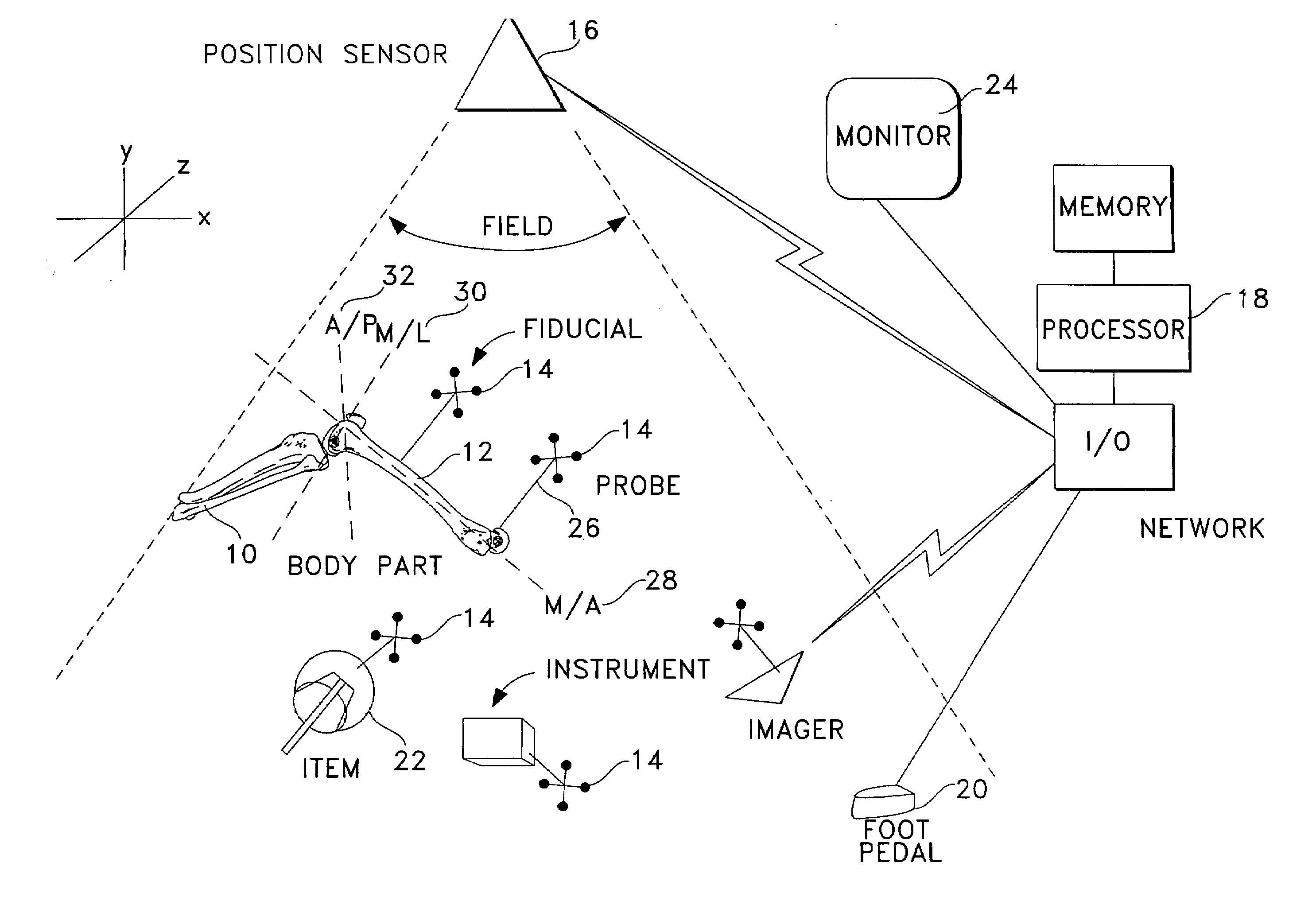
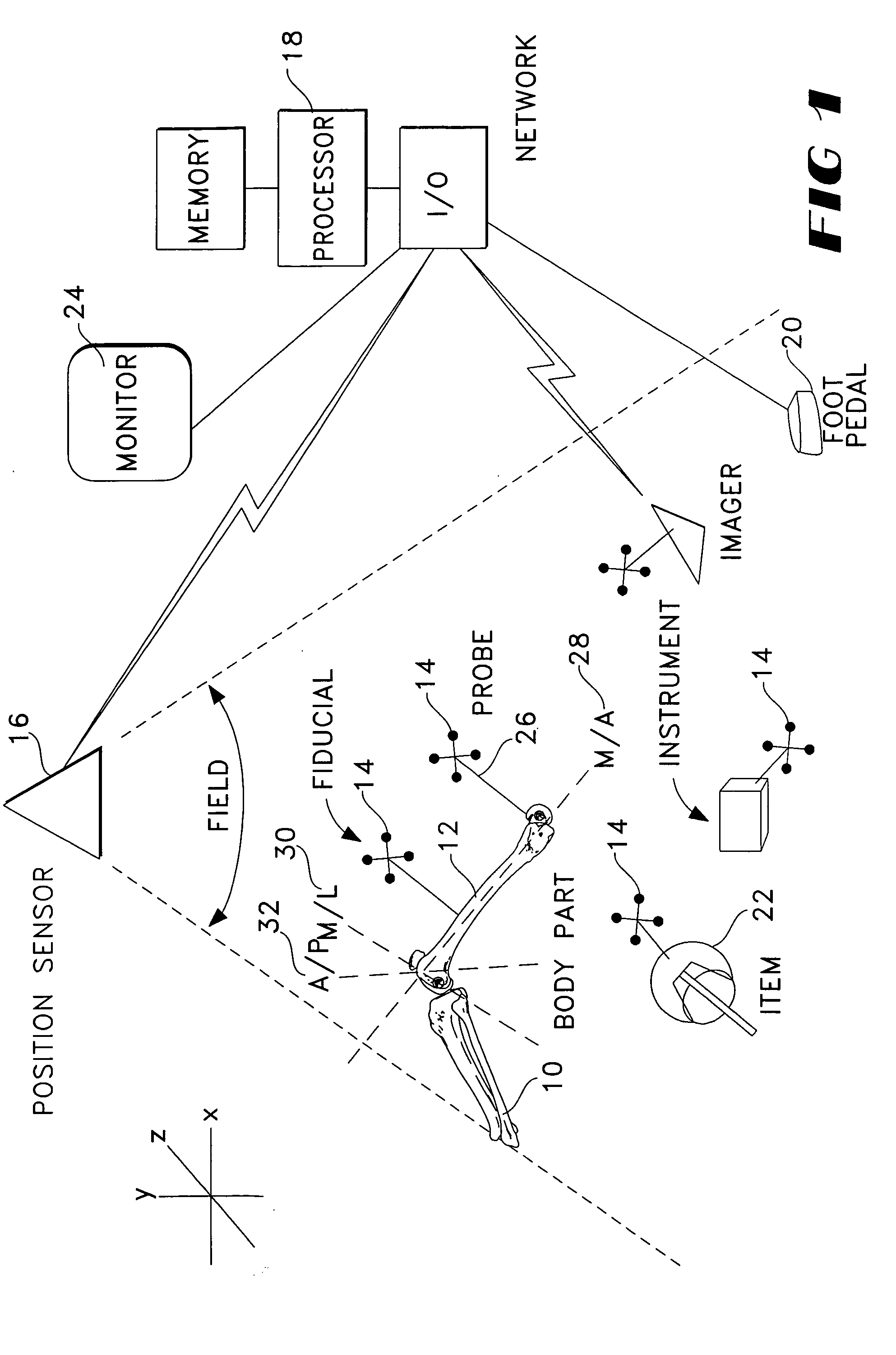
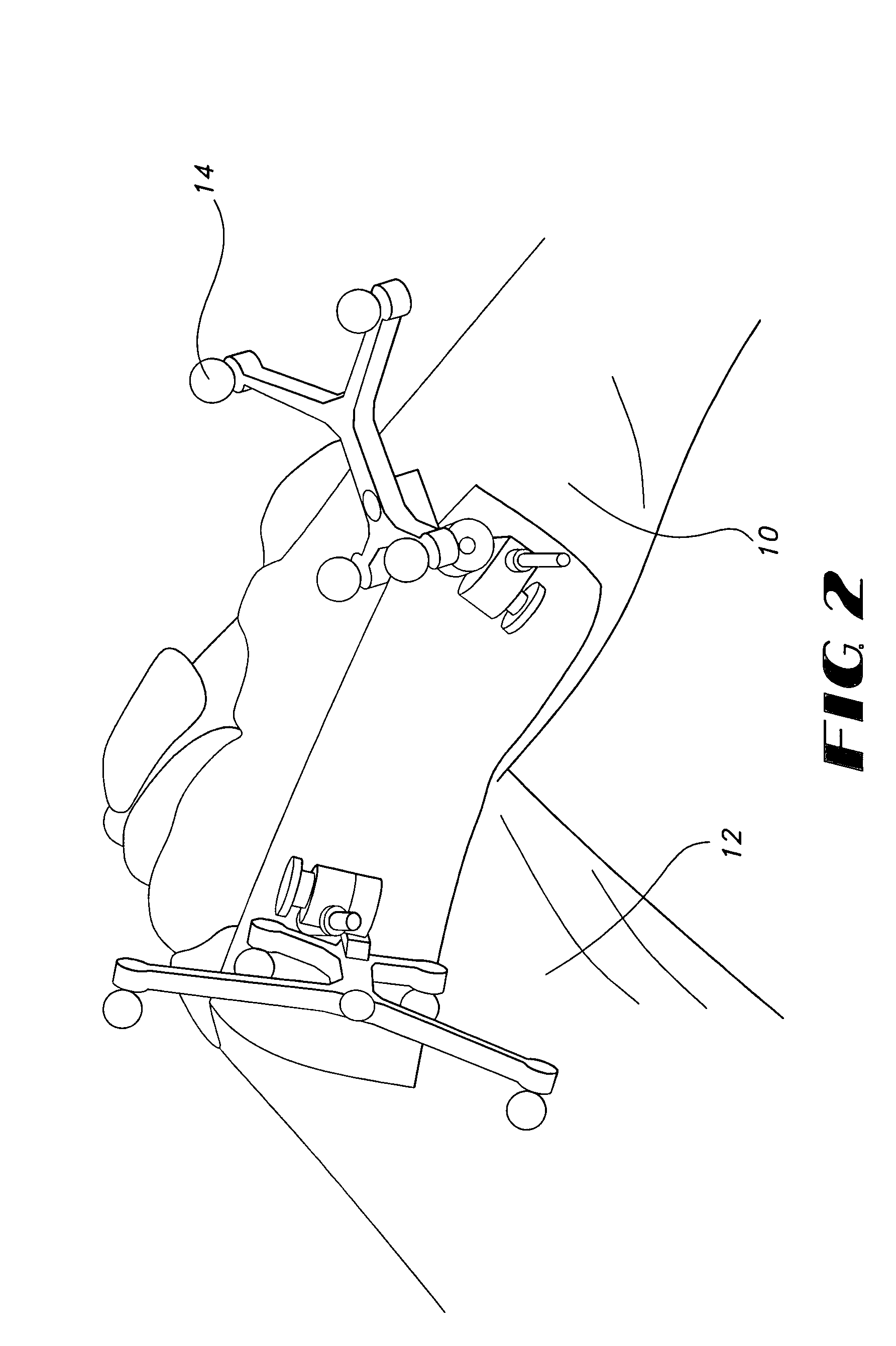
[0101]Instrumentation, systems, and processes according to a preferred embodiment of the present invention use computer capacity, including standalone and / or networked, to store data regarding spatial aspects of surgically related items and virtual constructs or references including body parts, implements, instrumentation, trial components, prosthetic components and rotational axes of body parts. Any or all of these may be physically or virtually connected to or incorporate any desired form of mark, structure, component, or other fiducial or reference device or technique which allows position and / or orientation of the item to which it is attached to be sensed and tracked, preferably in three dimensions of translation and three degrees of rotation as well as in time if desired. In the preferred embodiment, such “fidicuals” are reference frames each containing at least three, preferably four, sometimes more, reflective elements such as spheres reflective of lightwave or infrared energ...


PUM


Abstract

Instrumentation, systems, and processes for tracking anatomy, instrumentation, trial implants, implants, and references, and rendering images and data related to them in connection with surgical operations, for example total knee arthroplasties (“TKA”). These instrumentation, systems, and processes are accomplished by using a computer to intraoperatively obtain images of body parts and to register, navigate, and track surgical instruments. Disclosed in this document are also alignment modules and other structures and processes which allow for coarse and fine alignment of instrumentation and other devices relative to bone for use in connection with the tracking systems of the present invention.

Description

RELATED APPLICATION DATA[0001]This application claims priority to U.S. Ser. No. 10 / 084,012 filed on Feb. 27, 2002, which claims the benefit of U.S. Provisional Application No. 60 / 355,899 filed on Feb. 11, 2002 and U.S. Provisional Application No. 60 / 271,818 filed on Feb. 27, 2001.FIELD OF INVENTION[0002]Instrumentation, systems, and processes for tracking anatomy, implements, instrumentation, trial implants, implant components and virtual constructs or references, and rendering images and data related to them in connection with orthopedic, surgical and other operations, for example Total Knee Arthroplasty (“TKA”). Anatomical structures and such items may be attached to or otherwise associated with fiducial functionality, and constructs may be registered in position using fiducial functionality whose position and orientation can be sensed and tracked by systems and according to processes of the present invention in three dimensions in order to perform TKA. Such structures, items and ...

Claims


Application Information

Patent Timeline
Patent Type & Authority Patents(United States)
IPC IPC(8): A61F2/38A61B17/56A61B17/00A61B17/15A61B17/70A61B19/00A61F2/30A61F2/46
CPCA61B17/154A61B19/20A61B19/52A61B19/5244A61B17/70A61B19/50A61B19/56A61B2019/502A61B2019/505A61B2019/508A61B2019/5238A61B2019/5255A61B2019/5268A61B2019/5272A61B2019/5416A61B2019/5483A61B2019/562A61B2019/564A61B2019/566A61F2/38A61F2/3859A61F2/389A61F2/4657A61F2/4684A61F2002/30616A61F2002/30892A61F2002/4632A61B2090/3983A61B90/10A61B2034/102A61B90/36A61B2034/2055A61B2034/2068A61B2034/2072A61B2090/3916A61B2034/254A61B2034/256A61B34/20A61B34/25A61B2090/376A61B34/10A61B2034/105A61B2034/108A61B2034/252
Inventor CARSON, CHRISTOPHER PATRICKSMOTHERS, CRISTALYONS, CHRISTOPHER M.
Owner SMITH & NEPHEW INC
Learn More