Three-phase PWM-signal generating apparatus

a three-phase, signal generating technology, applied in the direction of electrical equipment, power conversion systems, ac-dc conversion, etc., can solve the problems of significant controllability degradation, achieve simple methods, reduce output voltage range limitation, and increase the holding time width of switching modes

Active Publication Date: 2009-06-16
MITSUBISHI ELECTRIC CORP
View PDF13 Cites 21 Cited by
  • Summary
  • Abstract
  • Description
  • Claims
  • Application Information

AI Technical Summary

Benefits of technology

[0046]According to the present invention, there is an effect that it is possible to increase a holding time width of a switching mode with a simple method with a less limitation of an output voltage range without adding a new device and it is possible to generate a three-phase PWM signal in a form of reducing a current detection limited range of a DC bus.

Problems solved by technology

This system has problems described below.
In these two cases, there is a problem in that, in a production section of a basic voltage vector with a short holding time width of a switching mode, since a sufficient DC current detection time cannot be secured and current detection cannot be performed correctly, controllability is deteriorated significantly.

Method used


Image

  • Three-phase PWM-signal generating apparatus
  • Three-phase PWM-signal generating apparatus
  • Three-phase PWM-signal generating apparatus

Examples


first embodiment

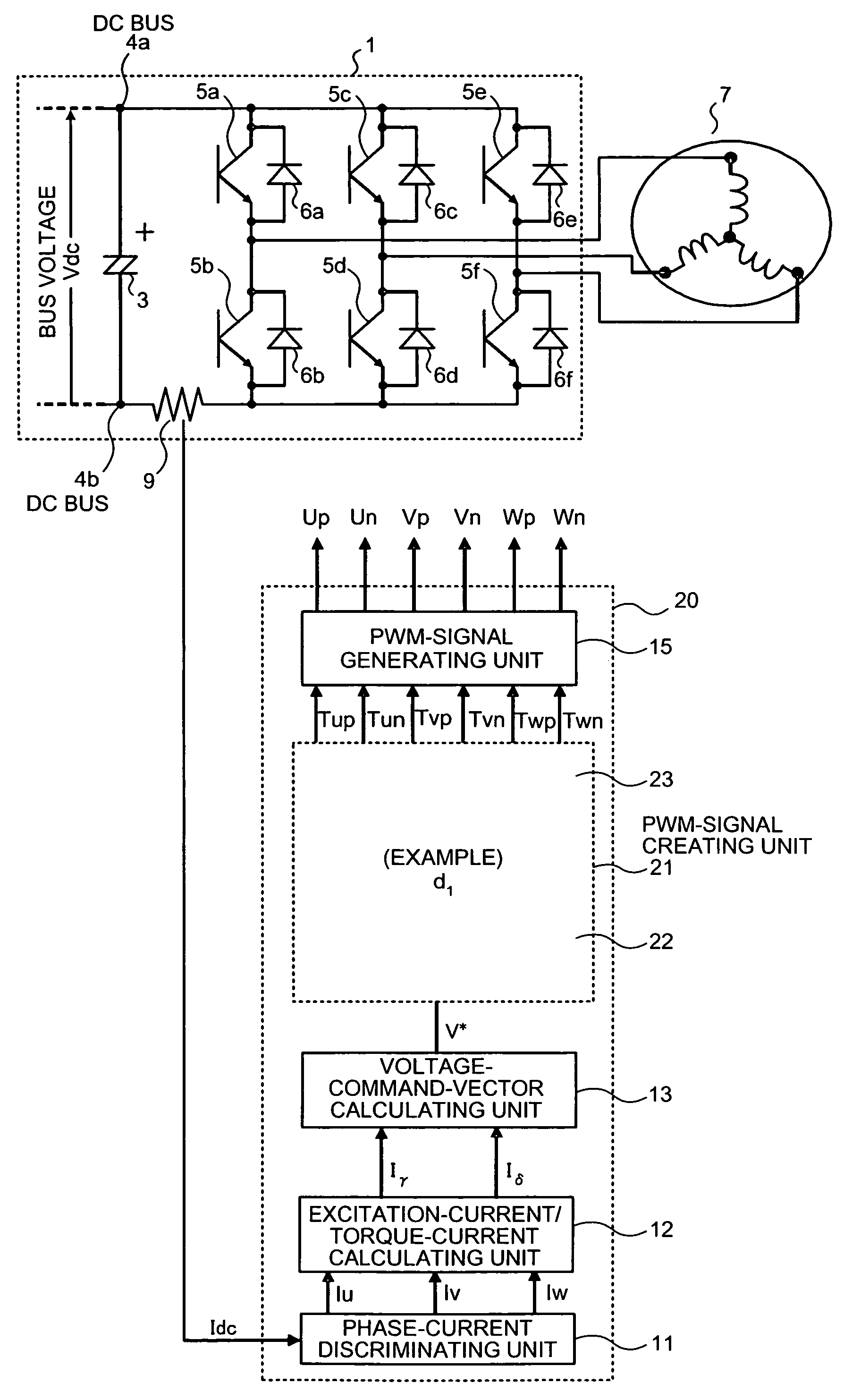
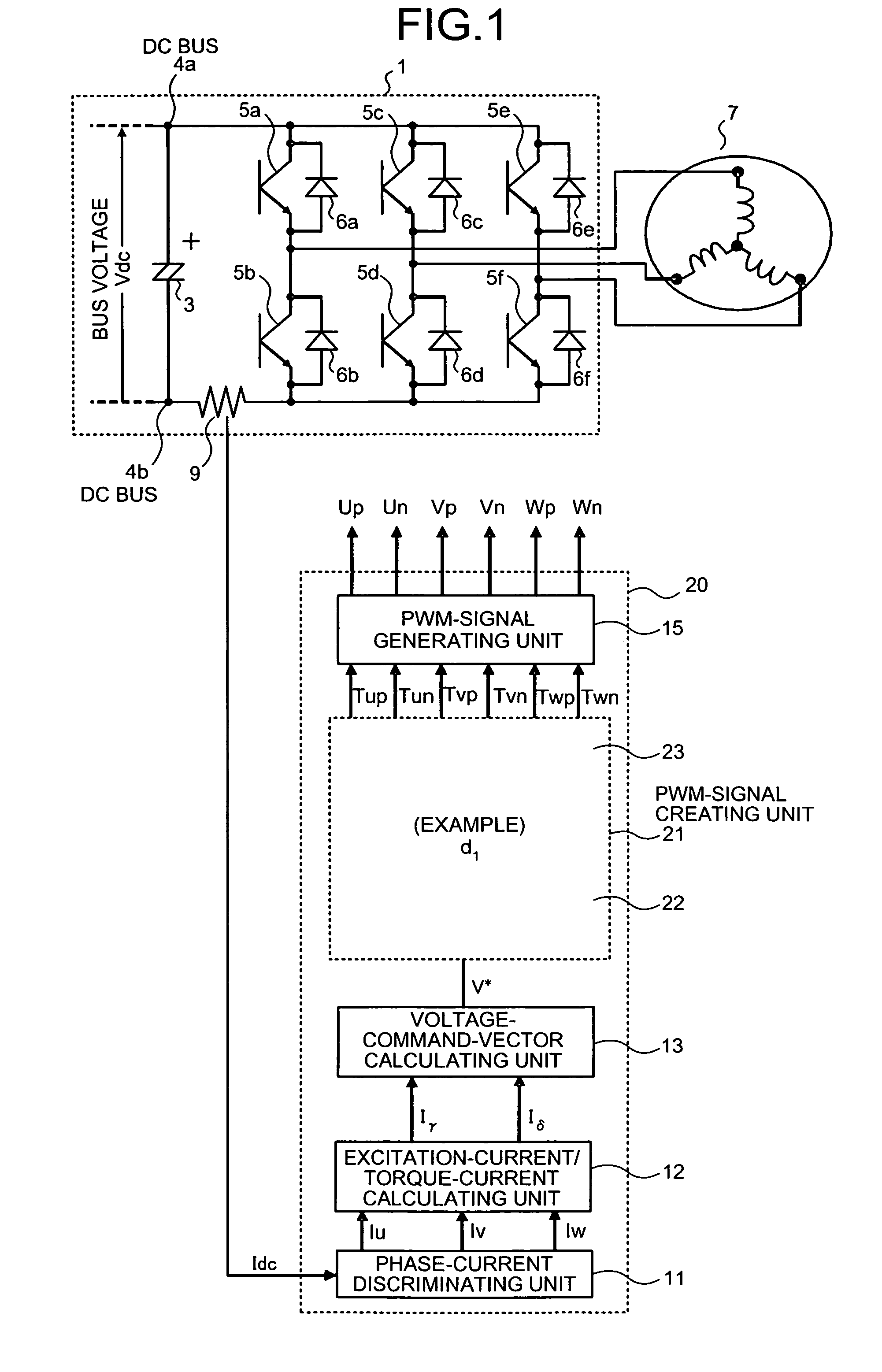
[0111]FIG. 1 is a block diagram of an inverter including a three-phase PWM-signal generating apparatus according to a first embodiment of the present invention. Note that, in FIG. 1, components identical with or equivalent to the components shown in FIG. 36 (the conventional example) are denoted by the identical reference numerals and signs. Sections related to the first embodiment are mainly explained here.

[0112]As shown in FIG. 1, in the first embodiment, an inverter control unit 20 is provided instead of the inverter control unit 2 in the constitution shown in FIG. 36 (the conventional example). In the inverter control unit 20, a PWM-signal creating unit 21 is provided instead of the PWM-signal creating unit 14 shown in FIG. 36 (the conventional example).

[0113]The PWM-signal creating unit 21 includes a PWM-signal-duty creating unit 22, which receives a voltage command vector V* from the voltage-command-vector calculating unit 13, and a PWM-signal-duty redistributing unit 23, whic...

second embodiment

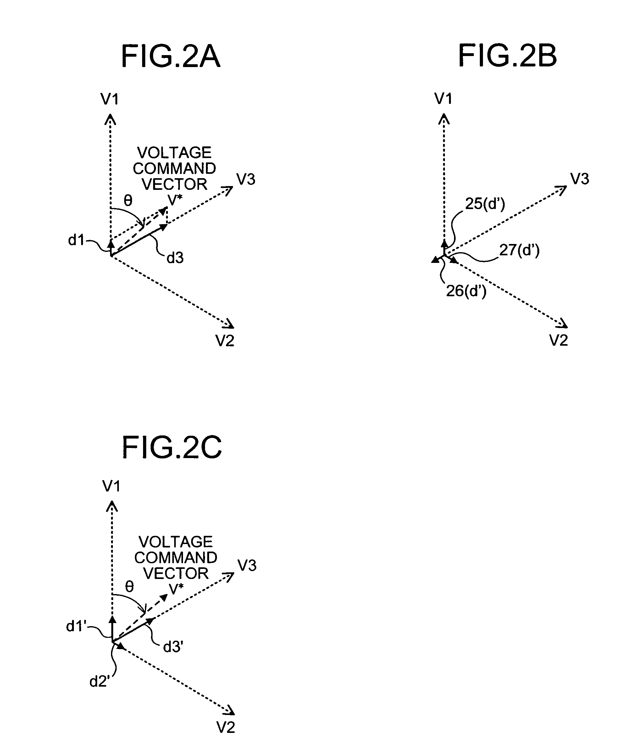
[0151]In an inverter including a three-phase PWM-signal generating apparatus according to a second embodiment of the present invention, a PWM-signal generating unit in the three-phase PWM-signal generating apparatus corresponds to the PWM-signal creating unit 21 in the constitution shown in FIG. 1 (the first embodiment). First, an operation of the PWM-signal-duty creating unit 22 is explained briefly with reference to FIGS. 1 and 2A, although the explanation is redundant.

[0152]As explained in the first embodiment, the PWM-signal-duty creating unit 22 decomposes the voltage command vector V* from the voltage-command-vector calculating unit 13 in directions of two basic voltage vectors on both sides of the voltage command vector V* to thereby generate production time ratios of the respective basic voltage vectors. In other words, the PWM-signal-duty creating unit 22 produces two kinds of basic voltage vectors with a phase difference of 60 degrees having the production time ratios as v...

third embodiment

[0178]FIGS. 28A to 28C are graphs for explaining, in an inverter including a three-phase PWM-signal generating apparatus according to a third embodiment of the present invention, an operation of a PWM-signal generating unit in the three-phase PWM-signal generating apparatus. In the third embodiment, a PWM signal is generated by the same method as the first and the second embodiment. However, an example of a constitution in securing an operation range on a low speed side of a motor is shown in the third embodiment. To facilitate understanding, in the explanation of the second embodiment, a PWM signal is generated by the method according to the first embodiment.

[0179]In the third embodiment, in the PWM-signal creating unit 21 in the constitution shown in FIG. 1 (the first embodiment), the PWM-signal-duty creating unit 22 performs the same operation as the first embodiment. However, the PWM-signal-duty redistributing unit 23 performs an operation different from the operation in the fir...


PUM


Abstract

An apparatus for generating a three-phase pulse-width-modulation signal for a three-phase voltage inverter employing a semiconductor switching element includes a generating unit that generates the three-phase pulse-width-modulation signal based on at least one combination of three basic voltage vectors and at least a zero vector.

Description

TECHNICAL FIELD[0001]The present invention relates to a three-phase pulse-width-modulation (PWM)-signal generating apparatus that generates a three-phase PWM signal for defining a switching mode set by a semiconductor switching element in a three-phase voltage inverter.BACKGROUND ART[0002]A three-phase voltage inverter is used for an inverter for, for example, an inverter for controlling to drive a motor of a refrigeration air conditioning apparatus. To facilitate understanding of the present invention, a constitution and an operation of a conventional inverter are explained below with reference to FIGS. 36 to 42.[0003]FIG. 36 is a block diagram of an example of the conventional inverter. The conventional inverter shown in FIG. 36 includes an inverter main circuit 1 and an inverter control unit 2 that generates a three-phase PWM signal that is a drive signal for a semiconductor switching element included in the inverter main circuit 1. In other words, the present invention relates t...

Claims


Application Information

Patent Timeline
Patent Type & Authority Patents(United States)
IPC IPC(8): H02M7/5387
CPCH02M7/53875H02M2007/53876H02M7/53876
Inventor ARISAWA, KOICHISAKANOBE, KAZUNORISHINOMOTO, YOSUKEYABE, MASAAKI
Owner MITSUBISHI ELECTRIC CORP
Why Eureka
Try Eureka