
System for maintaining hydrogen purity in electrical generators and method thereof

a technology of pure hydrogen and generator, which is applied in the direction of machines/engines, biological material analysis, process and machine control, etc., can solve the problems of increasing the cost of producing electricity by almost $4000 per day, 8% decrease in the purity of hydrogen in the generator, and replacing air with hydrogen

Active Publication Date: 2009-06-23
PROTON ENERGY SYST
View PDF14 Cites 11 Cited by
  • Summary
  • Abstract
  • Description
  • Claims
  • Application Information

AI Technical Summary

Benefits of technology

"The patent describes a system for maintaining the purity of hydrogen gas in an electrical power generator. The system includes a generator, a hydrogen generator, and a purity monitor that detects when the purity of the gas drops below a certain level. The system automatically compensates for any gas loss or contamination to ensure the generator operates at the desired efficiency level. The technical effect of this system is to provide a reliable and efficient source of energy for power generation while maintaining the purity of the hydrogen gas."

Problems solved by technology

However, as generator capacity and size increased, hydrogen replaced air due to its high heat capacity and low density.
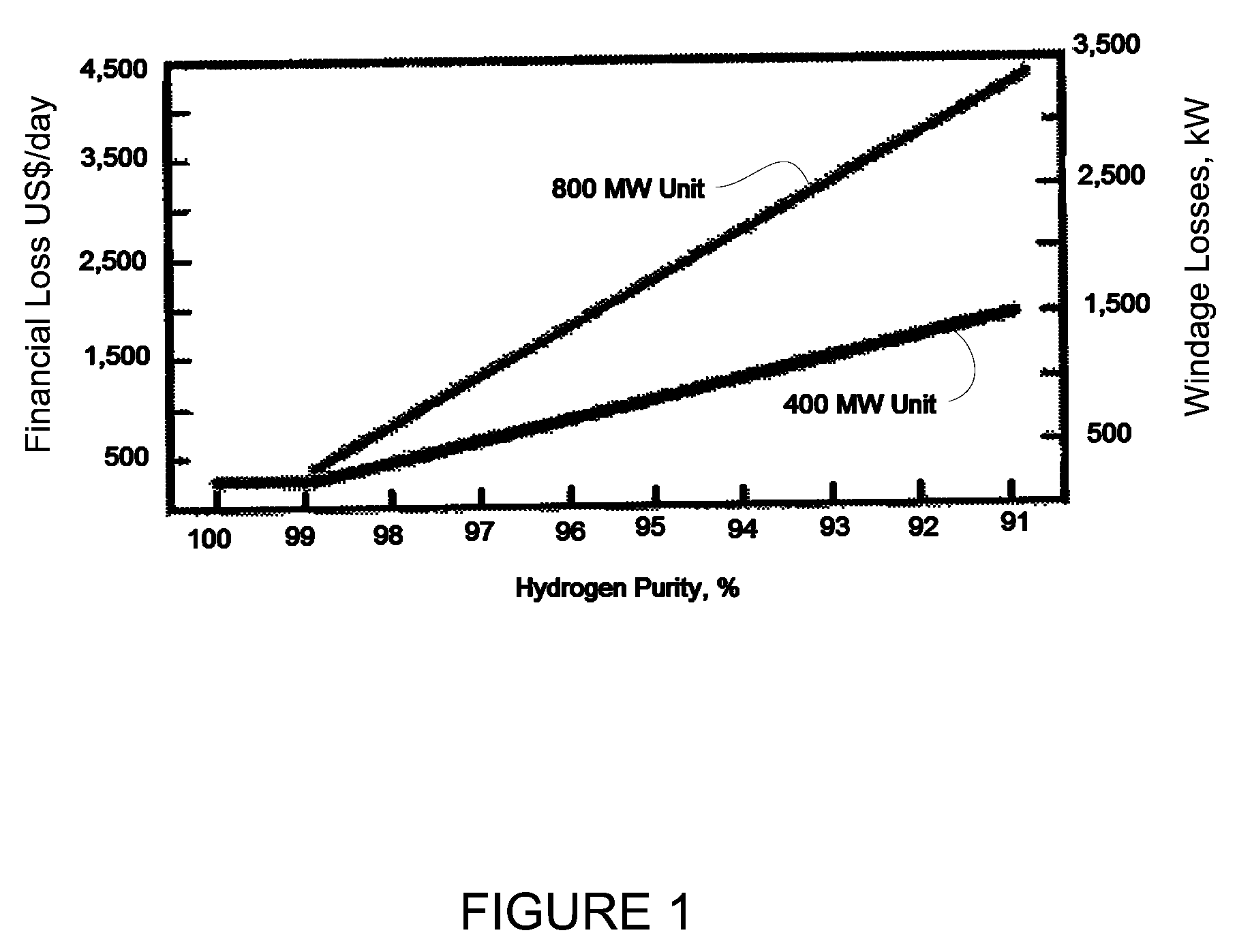
As shown in FIG. 1, as the windage loss increases due to impurities, the financial loss to the power plant correspondingly increases.
For a 800 MW generator, an 8% decrease in the purity of the hydrogen in the generator increases the cost of producing electricity by almost $4000 per day.
While the generator is in operation, hydrogen is continuously lost due to leaks in seals.
Typically, however, the electrolysis generators which are economically viable for providing makeup gas for the electrical generator lacked the capacity to produce sufficient volumes of hydrogen to quickly purge or fill the electrical generator after it had been shut down for maintenance.
Also, plant operators still relied on manual filling of the generators which did not allow for optimal efficiencies.

Method used


Image

  • System for maintaining hydrogen purity in electrical generators and method thereof
  • System for maintaining hydrogen purity in electrical generators and method thereof
  • System for maintaining hydrogen purity in electrical generators and method thereof

Examples


Embodiment Construction

[0017]As the demand for power by consumers has increased, electrical power producers have increasingly turned to larger generators to fulfill the needs of society. As the size of the generators increased, it became increasingly more difficult to maintain the generator at an appropriate operating temperature to prevent damage to the generator components. Smaller generators relied on air cooling to dissipate heat from the generator rotor windings. To improve heat transfer, generator manufacturers began to utilitize hydrogen gas as a transfer agent since the thermal conductivity of hydrogen is seven times that of air.

[0018]The switch to hydrogen also yielded side benefits by reducing the windage losses in the generator due to hydrogen's lower density. As shown in FIG. 1, the higher purity level of the hydrogen gas in the generator, the lower the windage losses. However, since the generator contains various components, such as seals which must be lubricated, contaminants such as water a...


PUM

PropertyMeasurementUnit
gas pressureaaaaaaaaaa
volumeaaaaaaaaaa
pressure Pdesaaaaaaaaaa

Abstract

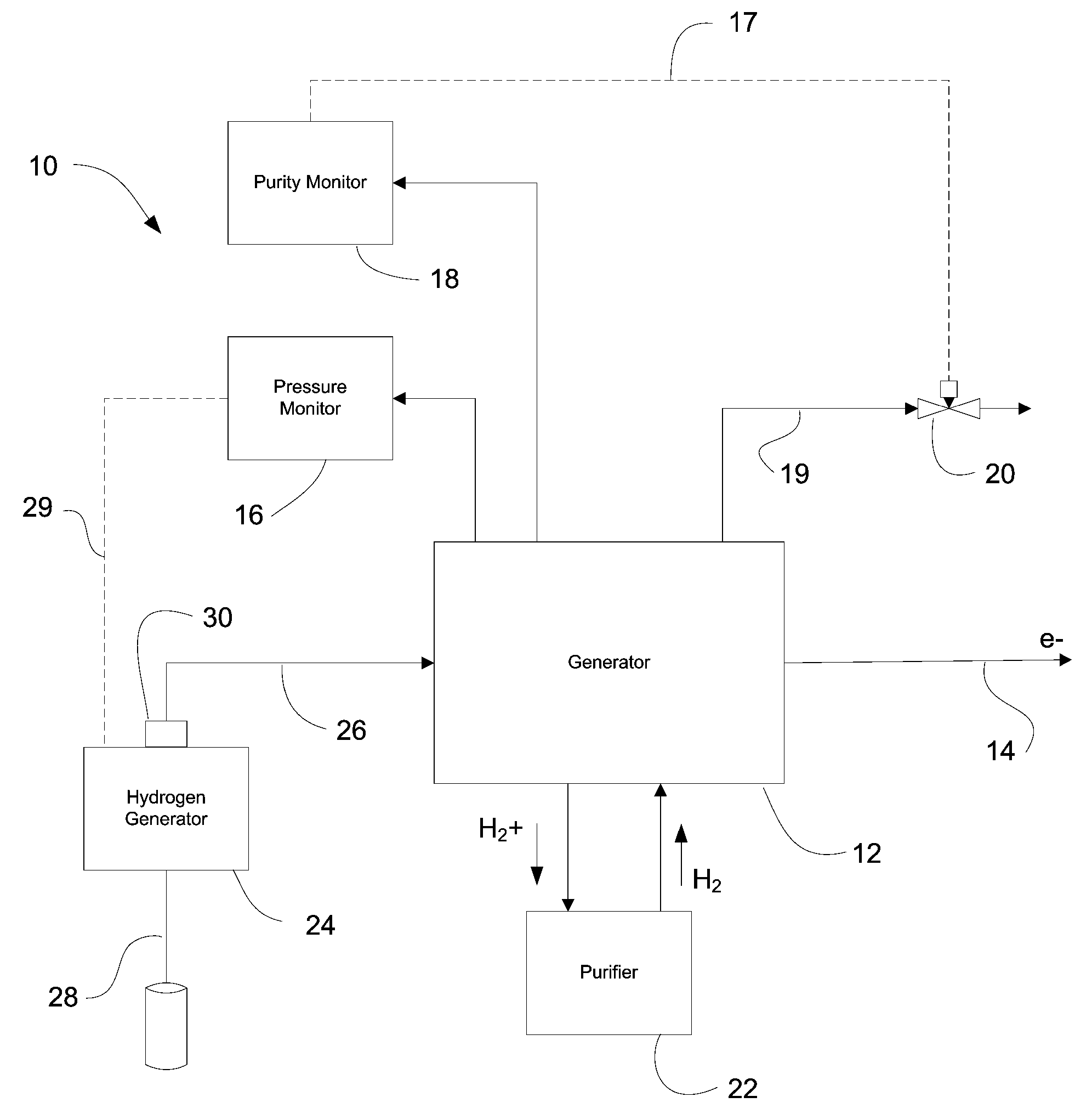
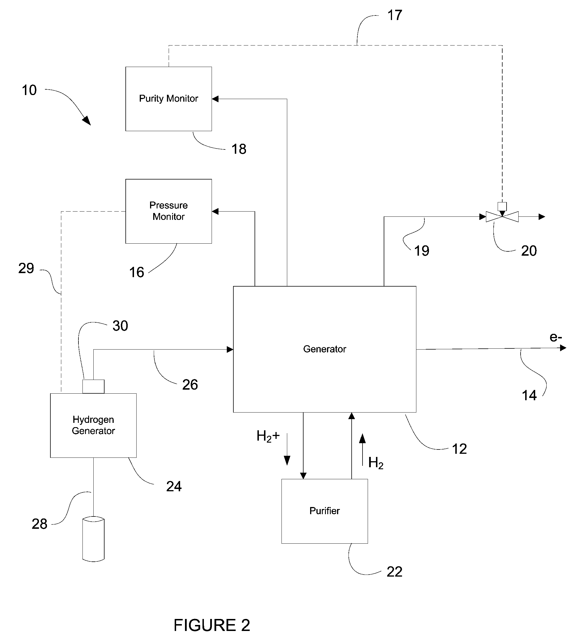
A method and apparatus is provided for an a system for maintaining hydrogen purity in an electrical power generator. The purity system includes: a generator, a hydrogen generator configured to provide hydrogen gas to the generator, a purity monitor for detecting the level of hydrogen purity in the generator and providing a signal when the purity drops below a predetermined threshold. The system automatically compensates for gas loss or contamination to maintain the desired level of efficiency in the electrical generator.

Description

FIELD OF INVENTION[0001]This disclosure relates generally to electrical generator systems and especially to electrical generators utilizing hydrogen gas to cool the generator.BACKGROUND OF THE INVENTION[0002]Modern electrical power plants often utilize turbine generators to produce electricity. During operation, these generators produce large amounts of heat which must be dissipated in order for the generators to operate at maximum efficiency. Traditionally, air was used as a cooling medium to help dissipate the heat. However, as generator capacity and size increased, hydrogen replaced air due to its high heat capacity and low density. Additionally, the use of hydrogen reduces the windage or friction losses over comparably sized air cooled units.[0003]Due to the loss in efficiency from windage, it is desirable to maintain as high a purity level of the hydrogen in the generator. As shown in FIG. 1, as the windage loss increases due to impurities, the financial loss to the power plant...

Claims


Application Information

Patent Timeline
Patent Type & Authority Patents(United States)
IPC IPC(8): C25B9/00C25B11/04C25B15/00G01N21/00G01N35/08H01M8/18H02K9/00
CPCG05D21/02Y10T436/12
Inventor SPERANZA, A. JOHNGUDINO, LUISA
Owner PROTON ENERGY SYST
Learn More