Organic electroluminescence display device

a technology of electroluminescent display and organic el, which is applied in the direction of luminescnet screens, discharge tubes, identification means, etc., can solve the problems of difficult to see organic el, and achieve the effect of high contrast and external light incident at the edges of emission regions

Active Publication Date: 2009-06-23
IDEMITSU KOSAN CO LTD
View PDF13 Cites 7 Cited by
  • Summary
  • Abstract
  • Description
  • Claims
  • Application Information

AI Technical Summary

Benefits of technology

[0007]The inventors of the invention conducted extensive studies in order to achieve the above object. As a result, the inventors have found that the amount of external light incident on the edges of the emission region of the organic EL device through the aperture region of the shielding layer can be reduced and, even if the incident external light is reflected / scattered at the edges of the emission region of the organic EL device, the reflected / scattered light can be prevented from escaping from the device by disposing the edges of the aperture region of the shielding layer closer to the center of the aperture region than the edges of the emission region of the organic EL device, whereby an organic EL display exhibiting high contrast can be obtained. This finding has led to the completion of the invention.
[0017]An organic EL display of the invention can suppress a decrease in contrast of the organic EL display caused by reflection / scattering of incident external light in the device.

Problems solved by technology

As a result, part of the reflected or scattered external light is emitted to the outside as display light and reaches the eyes of the viewer (human), whereby the organic EL display becomes difficult to see.
Therefore, since the contrast ratio decreases as the luminance during EL non-emission increases due to reflected or scattered external light, the organic EL display becomes difficult to see.

Method used


Image

  • Organic electroluminescence display device
  • Organic electroluminescence display device
  • Organic electroluminescence display device

Examples


example 1

(1) Fabrication of Organic EL Display

[0144]V259BK (manufactured by Nippon Steel Chemical Co., Ltd.) as the material for a shielding layer (a black matrix: BM) was applied by spin coating to a supporting substrate (OA2 glass manufactured by Nippon Electric Glass Co., Ltd.) having dimensions of 112×143×1.1 mm. Then, ultraviolet rays were applied through a photomask so that a lattice-shaped pattern (an aperture region (A) in the shielding layer:60×280 μm) was formed. The material was then developed using a 2% sodium carbonate aqueous solution and baked at 200° C. to obtain a black matrix (thickness: 1.0 μm) pattern.

[0145]V259G (manufactured by Nippon Steel Chemical Co., Ltd.) as the material for a green color filter was applied by spin coating. Then, ultraviolet rays were applied through a photomask aligned with the BM so that 320 rectangular stripe patterns (90-μm line and 240-μm gap) were obtained. The material was then developed using a 2% sodium carbonate aqueous solution and baked...

example 2

(1) Fabrication of Organic EL Display

[0171]V259G (manufactured by Nippon Steel Chemical Co., Ltd.) as the material for a green color filter was applied by spin coating to a supporting substrate (transparent substrate) (OA2 glass manufactured by Nippon Electric Glass Co., Ltd.) having dimensions of 112×143×1.1 mm. Then, ultraviolet rays were applied through a photomask so that 320 rectangular stripe patterns (90-μm line and 240-μm gap) were obtained. The material was then developed using a 2% sodium carbonate aqueous solution and baked at 200° C. to obtain a green color filter (thickness: 1.0 μm) pattern.

[0172]V259R (manufactured by Nippon Steel Chemical Co., Ltd.) as the material for a red color filter was applied by spin coating. Then, ultraviolet rays were applied through a photomask the green color filter (displaced at 110 μm pitch) adjacent so that 320 rectangular stripe patterns (90-μm line and 240-μm gap) were obtained. The material was then developed using a 2% sodium carbona...

example 3

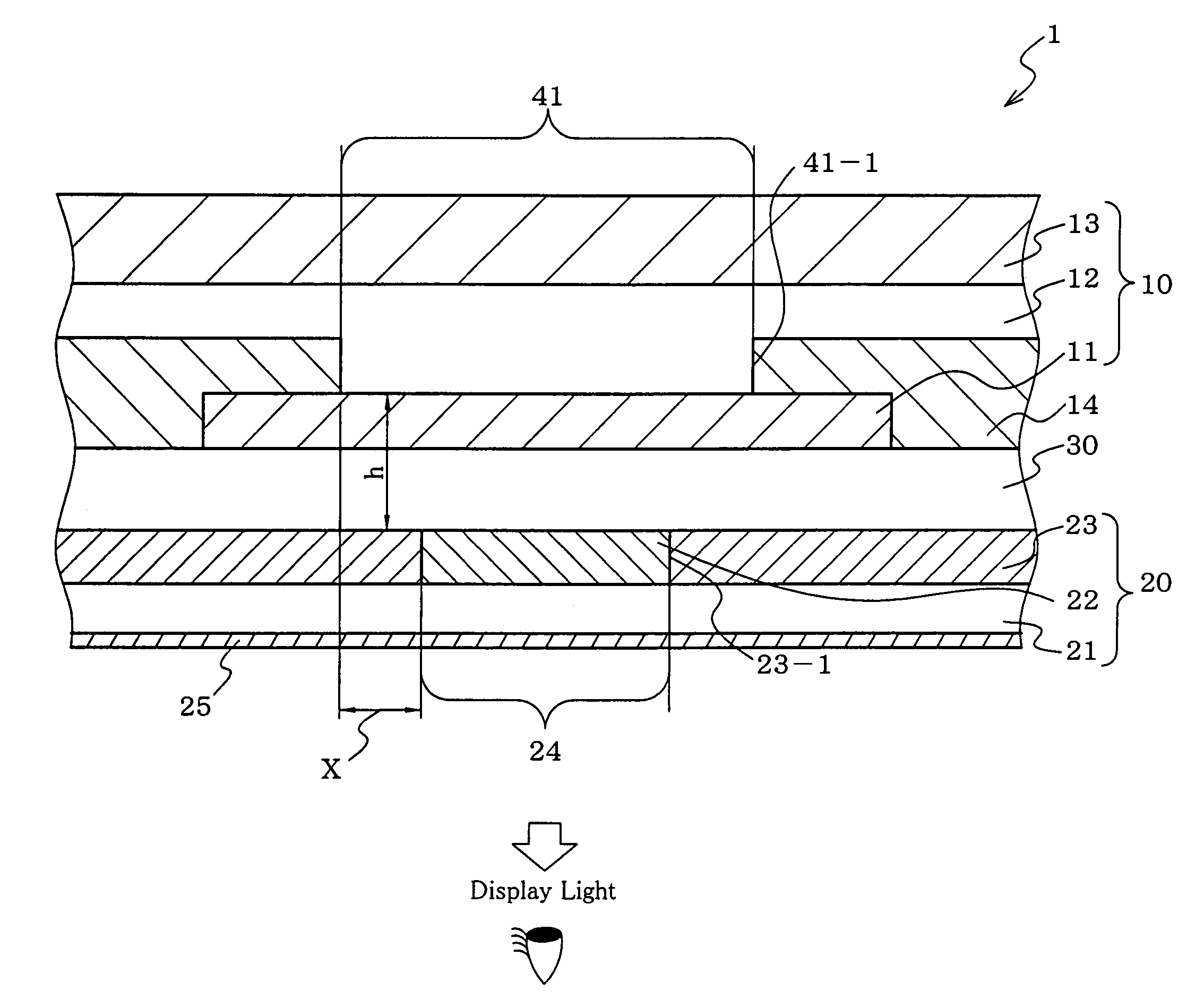
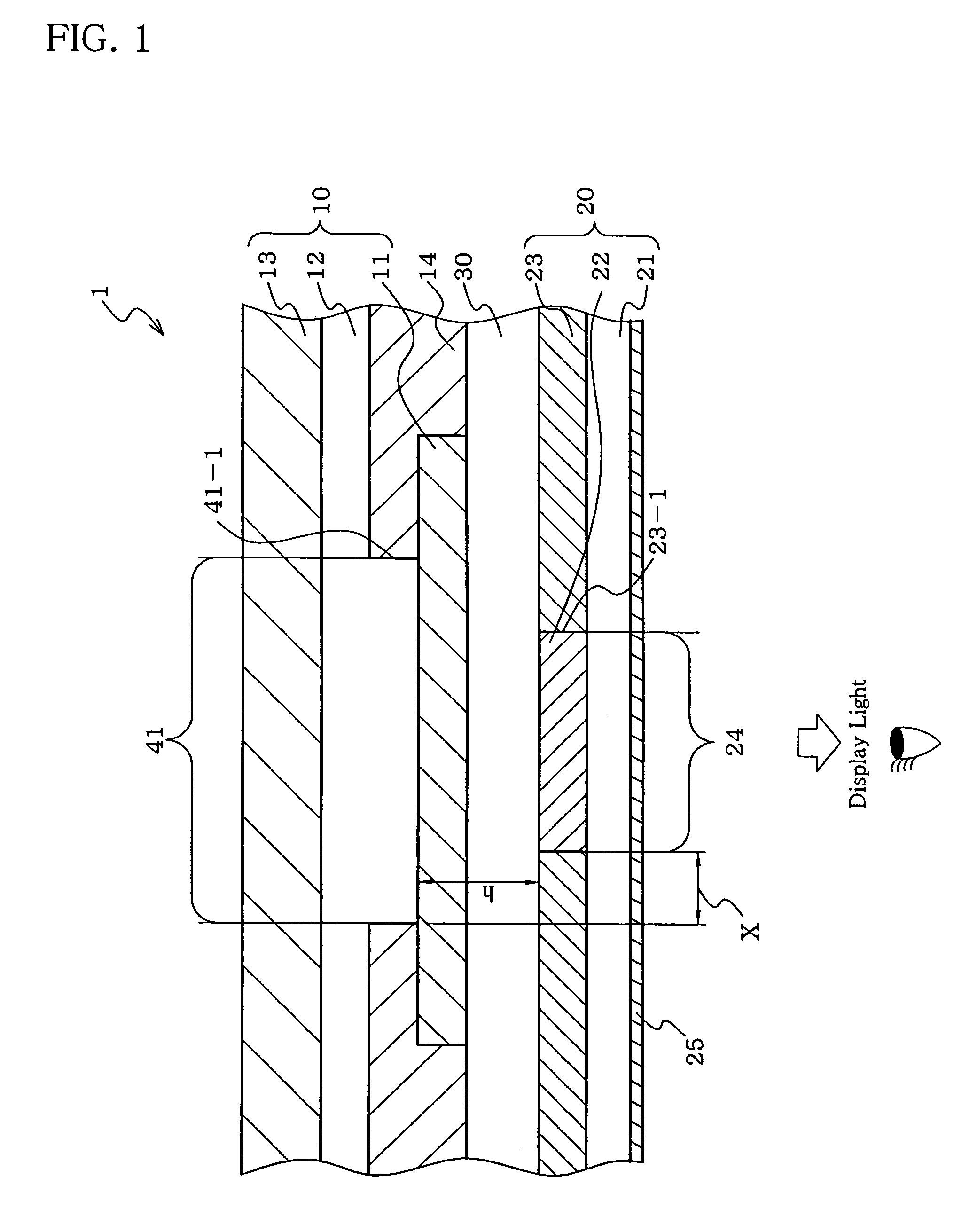
[0187]An organic EL display was fabricated under the same conditions as in Example 2 except that the thickness of a transparent medium (flattenizing film) was 6.8 μm.

[0188]The perpendicular distance h of the organic EL display was 7.0 μm, the overlapping part X was 5.0 μm and X / h was 0.71.

[0189]As a result of the contrast evaluation done in the same method as in Example 1, it was found that when fluorescent light of 1000 lux was illuminated, the contrast of the organic EL display was 100 (luminance during emission):1.0 (luminance during non-emission), that is, 100:1.


PUM


Abstract

An organic electroluminescent display (1) including: an organic electroluminescent device (10), and a color converting member (20) including a shielding layer (23) and a shielding layer aperture region (24) including a color converting layer (22), edges (23-1) of the aperture region (24) being closer to the center of the aperture region (24) than edges (41-1) of an emission region (41) of the organic electroluminescent device (10).

Description

TECHNICAL FIELD[0001]The invention relates to an organic electroluminescent display. More particularly, the invention relates to an organic electroluminescent display in which external light entering the display is prevented from being reflected / scattered in the device so that a decrease in contrast is suppressed.BACKGROUND ART[0002]In order to provide a practical organic electroluminescent (hereinafter may be abbreviated as “EL”) display, a display shown in FIG. 9 has been disclosed (see patent document 1, for example).[0003]In this organic EL display 9, the area of an aperture region 24 of a shielding layer (color converting layer 22) is increased in comparison with the area of an emission region 41 of an organic EL device 10 to allow light emitted from the organic EL device to efficiently enter the color converting layer, thereby improving the luminous efficiency of the organic EL display.[0004]However, since edges 23-1 of the shielding layer are positioned outside edges 41-1 of ...

Claims


Application Information

Patent Timeline
Patent Type & Authority Patents(United States)
IPC IPC(8): H01J1/62G09F9/30H01L27/32H01L51/52H05B33/02H05B33/12H05B33/14
CPCH01L51/5284H01L51/5281H01L27/322H01L27/3244H01L51/5275H10K59/38H10K59/12H10K50/858H10K50/86H10K50/865H05B33/02
Inventor EIDA, MITSURUKUMA, HITOSHI
Owner IDEMITSU KOSAN CO LTD
Why Eureka
Try Eureka