
Production test technique for RF circuits using embedded test sensors

a technology of test sensor and production test, which is applied in the direction of error detection/correction, resistance/reactance/impedence, instruments, etc., can solve the problem that the test technique requires much smaller test time and expensive measurement equipment, and achieve accurate diagnosis of sub-module specifications and small test time

Inactive Publication Date: 2009-06-30
GEORGIA TECH RES CORP
View PDF1 Cites 19 Cited by
  • Summary
  • Abstract
  • Description
  • Claims
  • Application Information

AI Technical Summary

Benefits of technology

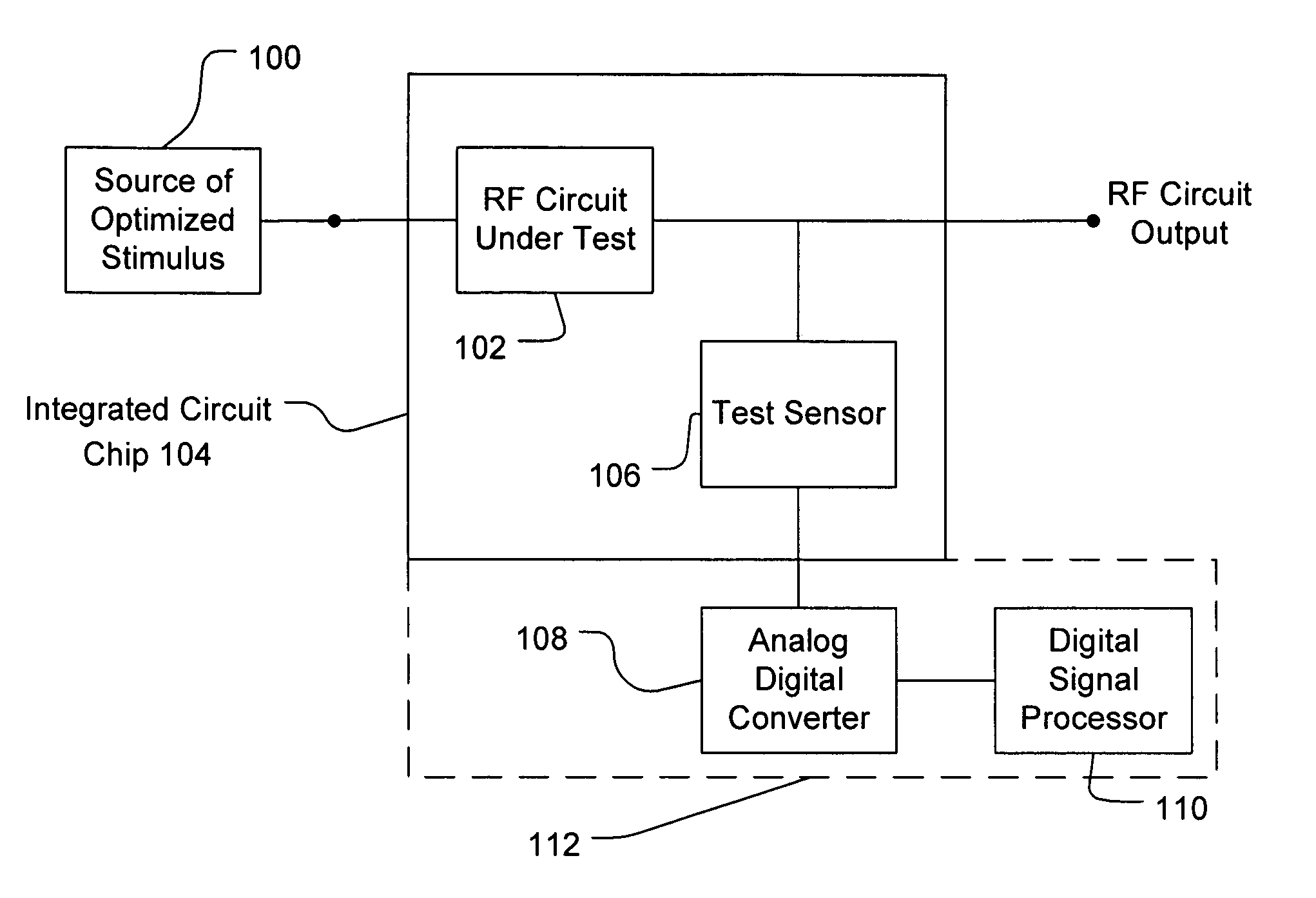
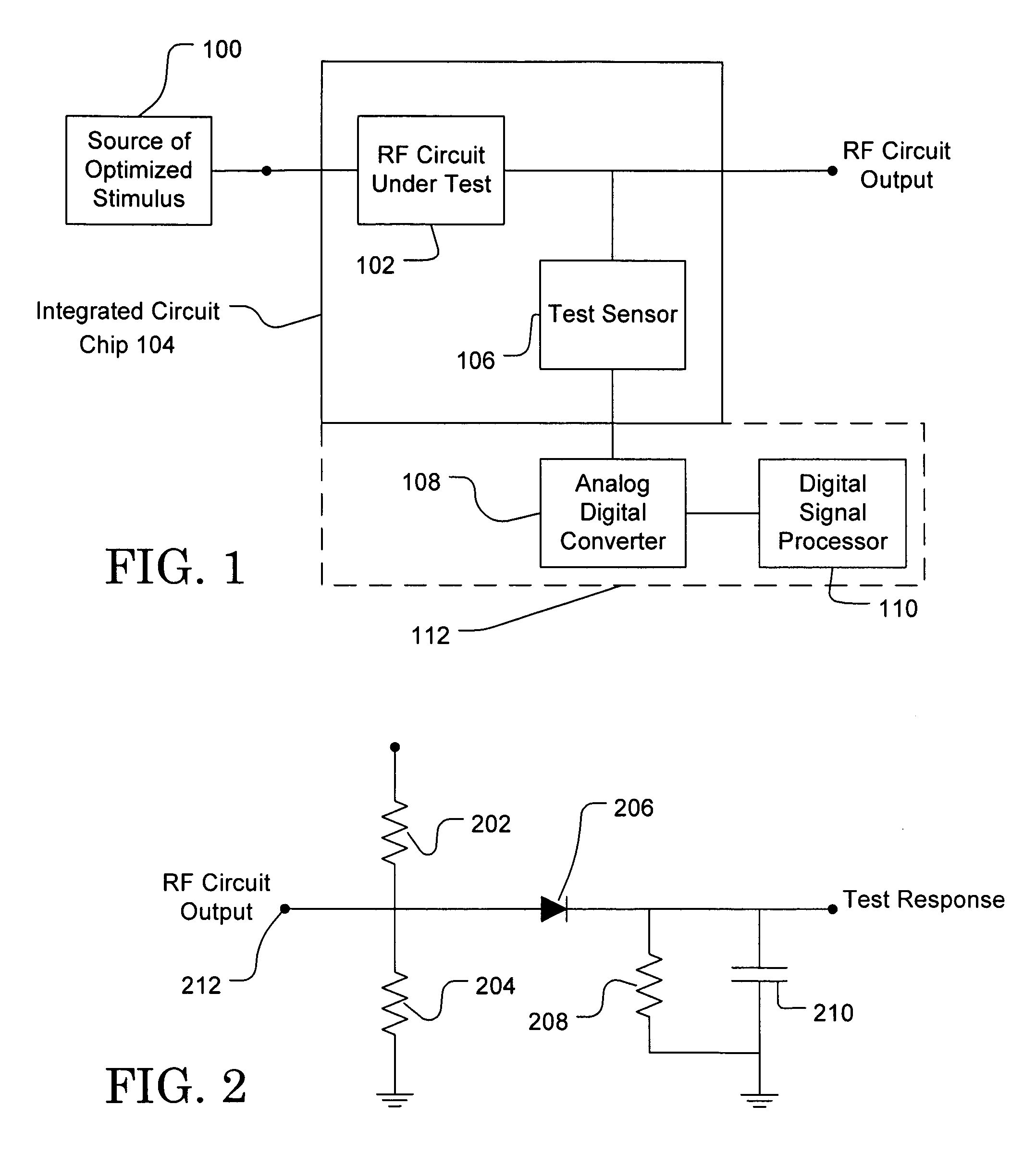
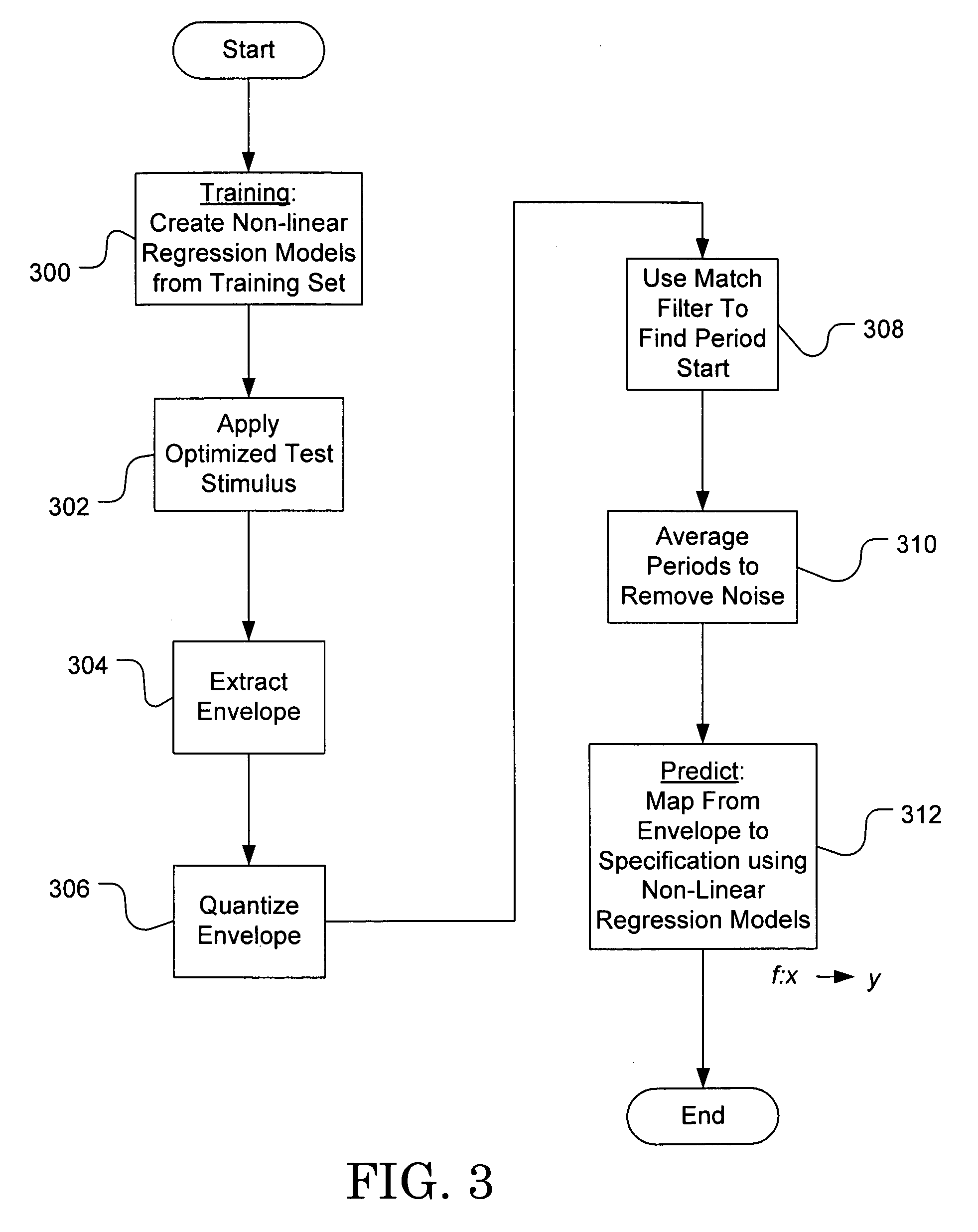
The present invention solves problems in testing RF circuits and devices by using a single test stimulus and embedded envelope detectors to estimate all the specification values of interest. The test makes use of the time-varying and low frequency envelope of the test response of the circuit under test. The test stimulus is optimized for a set of training circuits, and non-linear regression-based models are built from a set of specification values and envelopes of the test response signals to predict specification values of a circuit from its envelope signal response to the optimized stimulus. The test technique requires much smaller test time without expensive measurement equipment as compared to standard tests for RF systems and circuits, and accurate diagnosis of sub-module specifications is possible even when there are simultaneous performance perturbations in multiple modules.

Problems solved by technology

Second, the test technique requires much smaller test time without expensive measurement equipment as compared to standard tests for RF systems and circuits.

Method used


Image

  • Production test technique for RF circuits using embedded test sensors
  • Production test technique for RF circuits using embedded test sensors
  • Production test technique for RF circuits using embedded test sensors

Examples


Embodiment Construction

[0014]In the preferred embodiments of the invention, a built-in self test technique is implemented for extracting specifications of circuits and systems for wireless transceivers. With minimal external tester support, high quality built-in testing is performed with significant reduction of overall test time. The technique consists of deploying test sensors (envelope detectors) embedded inside the system and measuring the envelope of the output signal of the circuit responding to a single, optimized test stimulus. The envelope of the test response signal of the RF circuit is a relatively low frequency signal compared to the nominal operating frequency of the RF circuit under test, and can therefore be easily sampled using low-sampling-rate analog-to-digital converters. The output of the embedded sensor is highly correlated with the specifications of the circuit under test. Based on the test sensor output signals, the target specifications for individual modules as well as the system ...


PUM


Abstract

A single test stimulus and a simple test configuration with embedded envelope detectors are used to estimate all the specification values of interest for an RF circuit under test in an integrated circuit chip. Envelope detectors are deployed as sensors inside the circuit under test. Where more than one circuit is in an RF device in the integrated circuit, each RF circuit in the device may have its own envelope detector. A signal having, for example, time-varying envelopes is used as an optimized test stimulus. The test uses the time-varying and low frequency envelope of the test response. The circuit's response under test to the optimized test stimulus has features highly correlated with the specifications of interest. The test stimulus is optimized for a set of training circuits, and each training circuit in the set is selected to provide one of a spectrum of test responses to the stimulus.

Description

RELATED APPLICATIONS[0001]This patent application is based on Provisional Patent Application Ser. No. 60 / 696,201, filed Jul. 1, 2005, entitled Low Cost Production Test Technique of RF Circuits Using Envelope Detector, and claims the benefit of the filing date of the provisional patent application.TECHNICAL FIELD[0002]The invention relates to testing radio frequency (RF) circuits and systems, and more particularly to testing the circuits and systems with a testing technique making use of embedded test sensors.BACKGROUND OF THE INVENTION[0003]Advances in semiconductor manufacturing technology during the last decade have enabled integration of wireless transceiver systems into a single chip and provided low cost, system-level solutions. As the manufacturing cost has been reduced, production test cost has become an increasingly larger portion of the total manufacturing cost. In conventional test approaches, the specifications of the radio frequency (RF) system under test are measured an...

Claims


Application Information

Patent Timeline
Patent Type & Authority Patents(United States)
IPC IPC(8): G01R31/02
CPCG01R27/28G01R31/2822G01R31/2856
Inventor HAN, DONGHOONCHATTERJEE, ABHIJIT
Owner GEORGIA TECH RES CORP
Learn More