Resonator cavity configuration and method

a laser beam and configuration technology, applied in the direction of laser details, optical resonator shape and construction, active medium shape and construction, etc., can solve the problems of large problems, poor combined beam quality factor msup>2/sup>, and poor beam quality of high-power lasers, so as to improve beam quality, stability, and heat dissipation

Inactive Publication Date: 2009-06-30
YEDA RES & DEV CO LTD
View PDF67 Cites 14 Cited by
  • Summary
  • Abstract
  • Description
  • Claims
  • Application Information

AI Technical Summary

Benefits of technology

[0023]There is a need in the art to obtain high-power laser characterized by improved beam quality, stability, and heat dissipation.
[0024]The present invention solves the above problems by providing a novel approach for intra-cavity coherent addition of two or more laser beams that enables stable operation. The present invention takes advantage of synchronizing and coherently adding two or more laser oscillators (with one or more gain media), to produce a higher power output, and utilizes various new intra-cavity couplers and resonator cavity configurations in order to add two or more TEM00 mode beams, two or more single high-order-transverse-mode beams, and two or more transverse multimode beams.
[0025]Additionally, the technique of the present invention enables one laser beam with the lowest transverse modal content to impose its low transverse modal content on the other participating laser beam(s), so that all beams can be phase locked, as well as phase locked and added coherently within the laser cavity.
[0026]The present invention also provides for unique couplers incorporated in a laser cavity for coupling between beams propagating through the laser cavity. Such coupler could contain several optical elements on a single glass substrate, and is thus extremely compact and stable against vibrations and thermal drifts.
[0037]Generally, the need for anti-reflecting coatings can be eliminated by orienting the beam coupler at a Brewster angle with respect to the cavity axis, and by operating with a specific linear polarization of light.

Problems solved by technology

High-power lasers are typically characterized by inferior beam quality, stability, and heat dissipation, as compared to that of lower power lasers.
Combining several low-power lasers by incoherently adding the field distributions of several laser output beams results in that the combined beam-quality factor M2) is relatively poor with low optical brightness.
When coherently combining two or more laser output fields, two major difficulties are encountered.
Such coupling typically introduces excessive losses to each laser field, and requires very accurate relative alignment.
The second (and somewhat related) difficulty results from the need for accurately controlling the relative phase between the different laser fields, so as to ensure constructive interference between them.
This requires that the distances between the participating optical components must be very accurately controlled, causing the output power to be extremely sensitive to thermal drifts and acoustic vibrations.
This approach, however, is applicable only in fiber laser systems, and designed only for single TEM00 beams.

Method used


Image

  • Resonator cavity configuration and method
  • Resonator cavity configuration and method
  • Resonator cavity configuration and method

Examples


Embodiment Construction

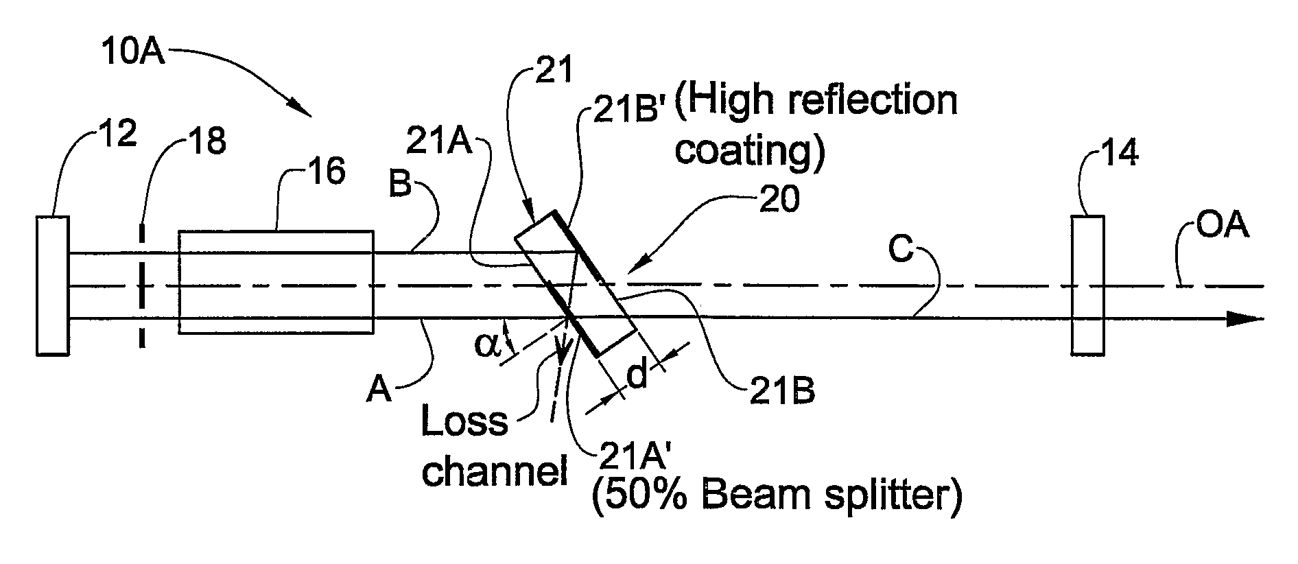
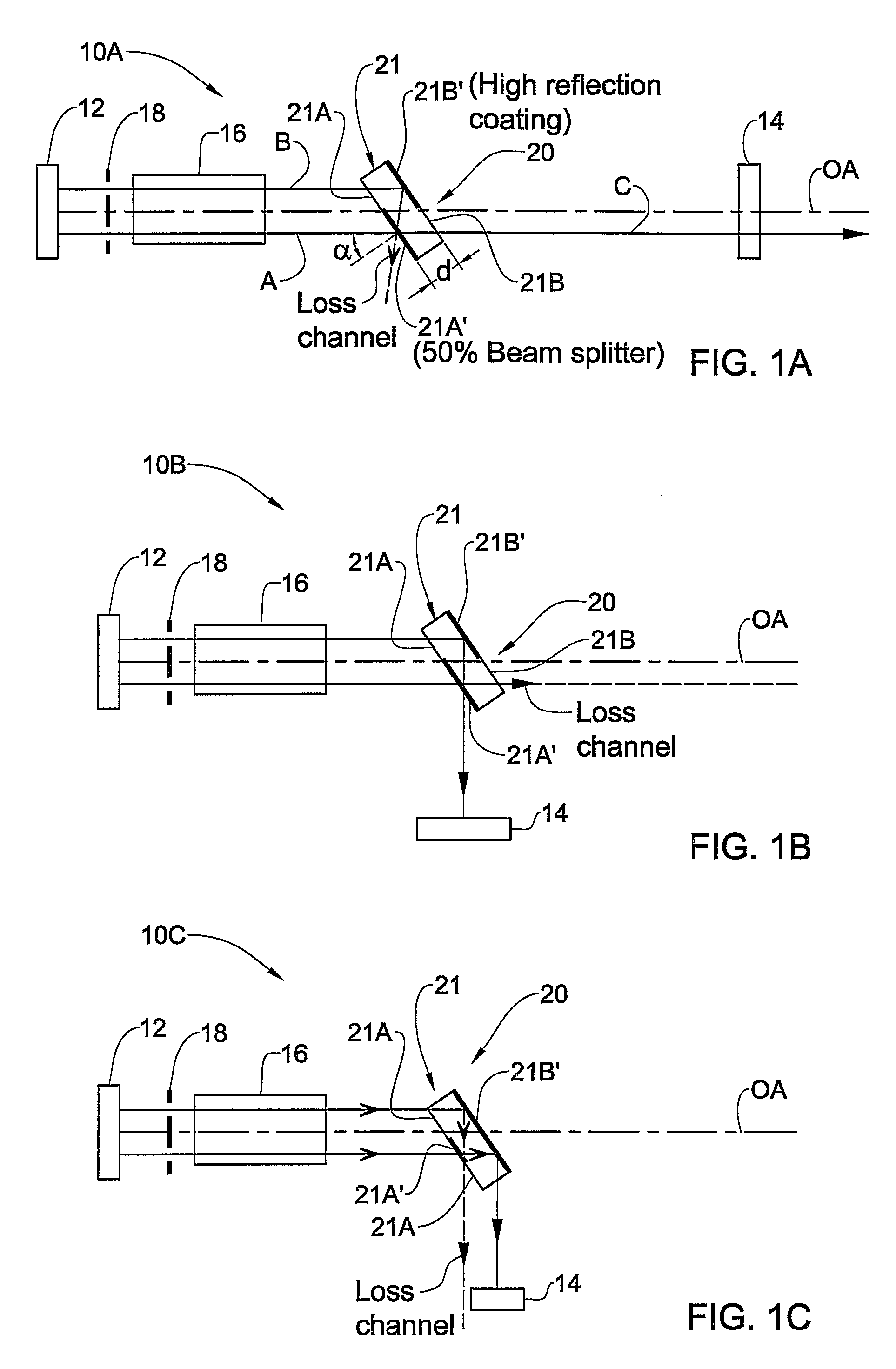
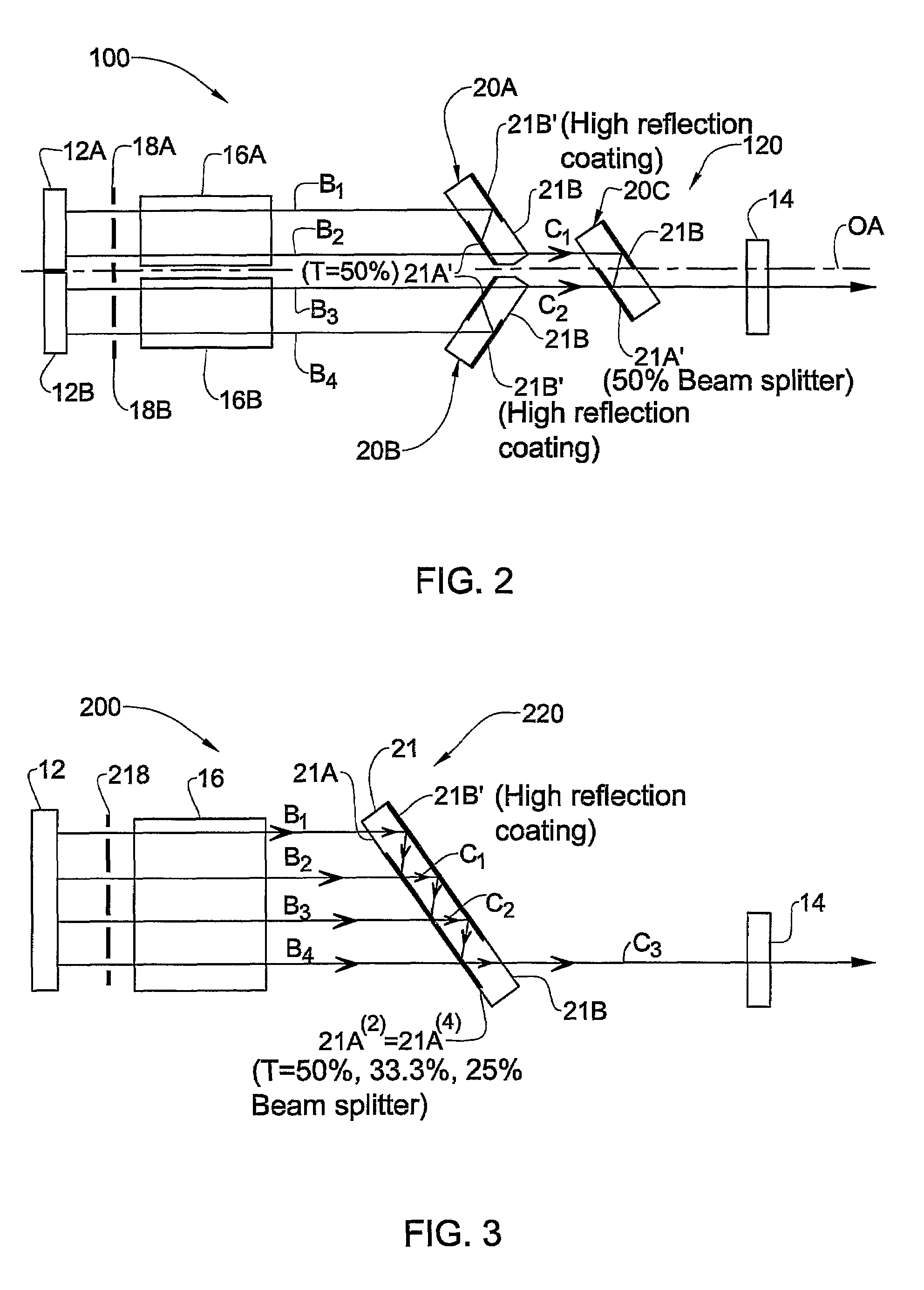
[0077]The present invention provides for a novel method for light propagation in resonator cavity and novel resonator cavity configuration enabling intra-cavity phase locking, or intra-cavity phase locking and coherent addition, of two or more laser beams. Various examples of the laser cavity configurations of the present invention are described below. The configurations, as well as light propagation schemes, are shown in the figures schematically, and it should be understood that these configurations could be realized with basically all types of stable resonators (various mirror curvatures or other intracavity optical elements), with various types of gain mediums (gas, solid-state, diode, fiber, etc.), with various types of operational methods (CW, pulsed free running, Q-switched pulsed, etc.), etc.

[0078]Referring to FIG. 1A, there is schematically illustrated an example of a resonator cavity, generally at 10A, configured for intra-cavity phase locking and coherent addition of two ...


PUM


Abstract

A resonator cavity (10A) and method and presented. The resonator cavity (10A) comprises at least one gain medium (16) and end reflectors (12, 14) which define together longitudinal modes of light in the cavity, and further comprises an intra-cavity beam coupler assembly (20). The beam coupler assembly (20) is configured to split light impinging thereon into a predetermined number of spatially separated light channels, and to cause phase locking and at least partial coherent combining of the light channels, having common longitudinal and transverse modes, in a double pass through the beam coupler assembly (20). The resonator cavity (10A) is configured and operable to produce at least one output combined light channel of a predetermined intensity profile.

Description

[0001]This is a National Phase Application filed under 35 U.S.C. 371 as a national stage of PCT / IL2004 / 001141, with the filing date of Dec. 16, 2004, an application claiming the benefit under 35 USC 119(e) U.S. Provisional Patent Application No. 60 / 530,259 filed on Dec. 18, 2003, the entire content of which is hereby incorporated by reference in its entirety.FIELD OF THE INVENTION[0002]This invention relates to a resonator cavity configuration and a method of laser beam generation.LIST OF REFERENCES[0003]The following references are considered to be pertinent for the purpose of understanding the background of the present invention:[0004][1] M. Jr. DiDomenico, “A single-frequency TEM00—mode gas laser with high output power”, Appl Phys. Lett. 8, no. 1, 20-22 (1966).[0005][2] M. Jr. DiDomenico, “Characteristics of a single-frequency Michelson-type He—Ne gas laser”, IEEE JQE QE-2, no. 8, 311-322 (1966).[0006][3] M. Brunel, A. Le Floch and F. Bretenaker, “Multiaxis laser eigenstates”, J....

Claims


Application Information

Patent Timeline
Patent Type & Authority Patents(United States)
IPC IPC(8): H01S3/13H01S3/08H01SH01S3/07H01S3/10H01S3/23H01S5/40
CPCH01S3/07H01S3/0805H01S3/08063H01S3/10H01S3/1106H01S3/08054H01S3/08059H01S3/08068H01S3/0811H01S3/0816H01S3/082H01S3/10092H01S3/1307H01S3/2383H01S5/4012H01S5/4025H01S5/4062
Inventor ISHAAYA, AMIEL A.DAVIDSON, NIRFRIESEM, ASHER A.SHIMSHI, LIRAN
Owner YEDA RES & DEV CO LTD
Why Eureka
Try Eureka