Methods and apparatus for vertebral stabilization using sleeved springs

a technology of vertebral stabilization and sleeve springs, which is applied in the field of vertebral stabilization of a spine using springs, can solve the problems of compromising a person's quality of life, most common and often debilitating conditions affecting millions of people, and back pain

Active Publication Date: 2009-07-07
ALTUS PARTNERS
View PDF32 Cites 102 Cited by
  • Summary
  • Abstract
  • Description
  • Claims
  • Application Information

AI Technical Summary

Problems solved by technology

Back pain is one of the most common and often debilitating conditions affecting millions of people in all walks of life.
Approximately half of those suffering from persistent back pain are afflicted with chronic disabling pain, which seriously compromises a person's quality of life and is the second most common cause of worker absenteeism.
Further, the cost of treating chronic back pain is very high, even though the majority of sufferers do not receive treatment due to health risks, limited treatment options and inadequate therapeutic results.
Thus, chronic back pain has a significantly adverse effect on a person's quality of life, on industrial productivity, and on heath care expenditures.
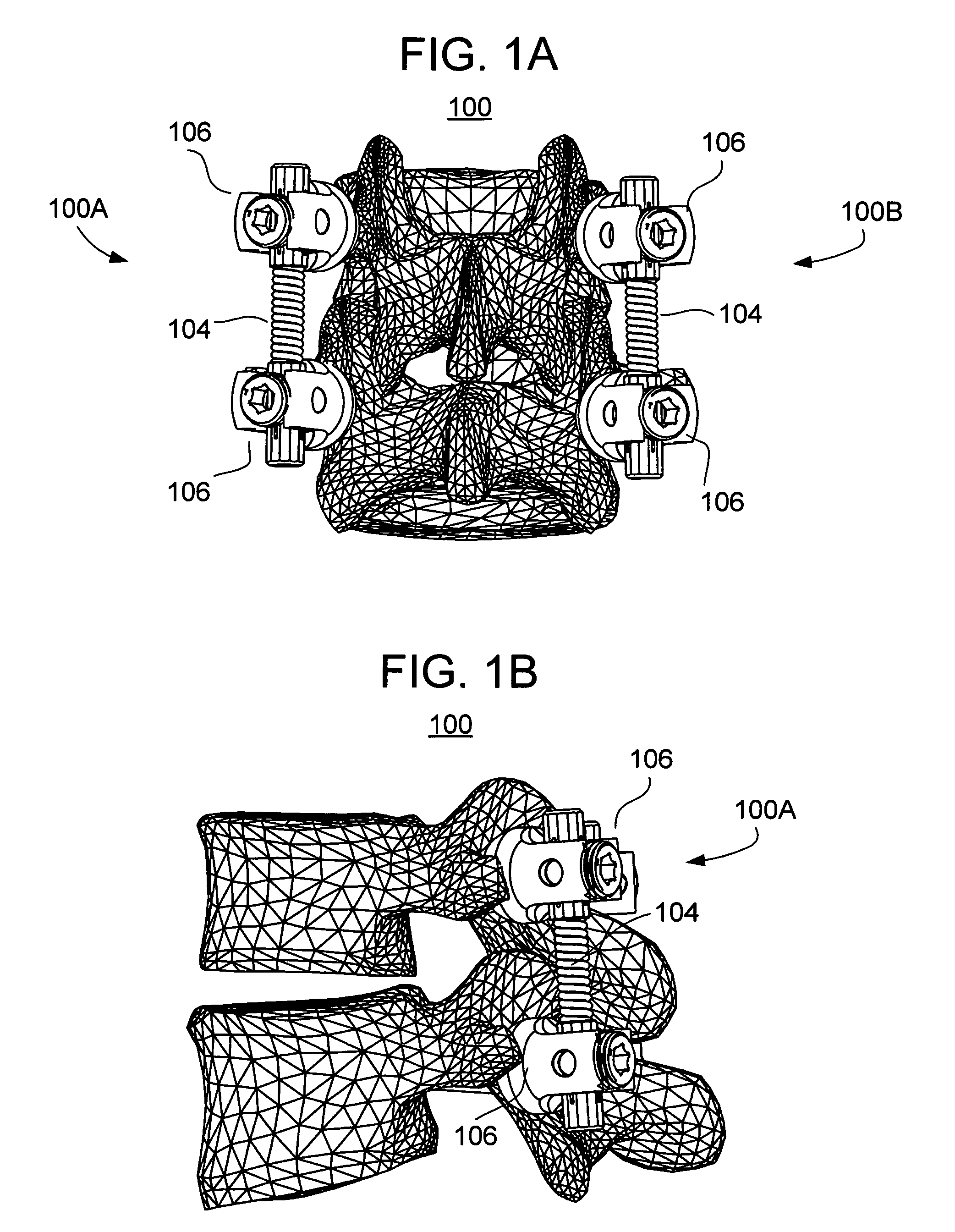
However, following the surgical procedure, fusion takes additional time to achieve maximum stability and a spinal fixation device is typically used to support the spinal column until a desired level of fusion is achieved.
However, because the connection units prevent normal movement of the spinal column, after prolonged use, the spinal fixation device can cause ill effects, such as “junctional syndrome” (transitional syndrome) or “fusion disease” resulting in further complications and abnormalities associated with the spinal column.
In particular, due to the high rigidity of the rods or plates used in conventional fixation devices, the patient's fixed joints are not allowed to move after the surgical operation, and the movement of the spinal joints located above or under the operated area is increased.
Consequently, such spinal fixation devices cause decreased mobility of the patient and increased stress and instability to the spinal column joints adjacent to the operated area.
It has been reported that excessive rigid spinal fixation is not helpful to the fusion process due to load shielding caused by rigid fixation.
However, because these devices are intended for use following a bone fusion procedure, they are not well-suited for spinal fixation without fusion.
Thus, in the end result, these devices do not prevent the problem of rigid fixation resulting from fusion.
Thus, it is effective in selected cases but is not appropriate for cases that require greater stability and fixation.
However, it has not yet been determined whether the Dynesys device can maintain long-term stability with flexibility and durability in a controlled study.
Because it has polyethylene components and interfaces, there is a risk of mechanical failure.
Furthermore, due to the mechanical configuration of the device, the surgical technique required to attach the device to the spinal column is complex and complicated.
These devices are flexible but they are not well-suited for enduring long-term axial loading and stress.
The design of existing flexible fixation devices are not well suited to provide varying levels of flexibility to provide optimum results for each individual candidate.
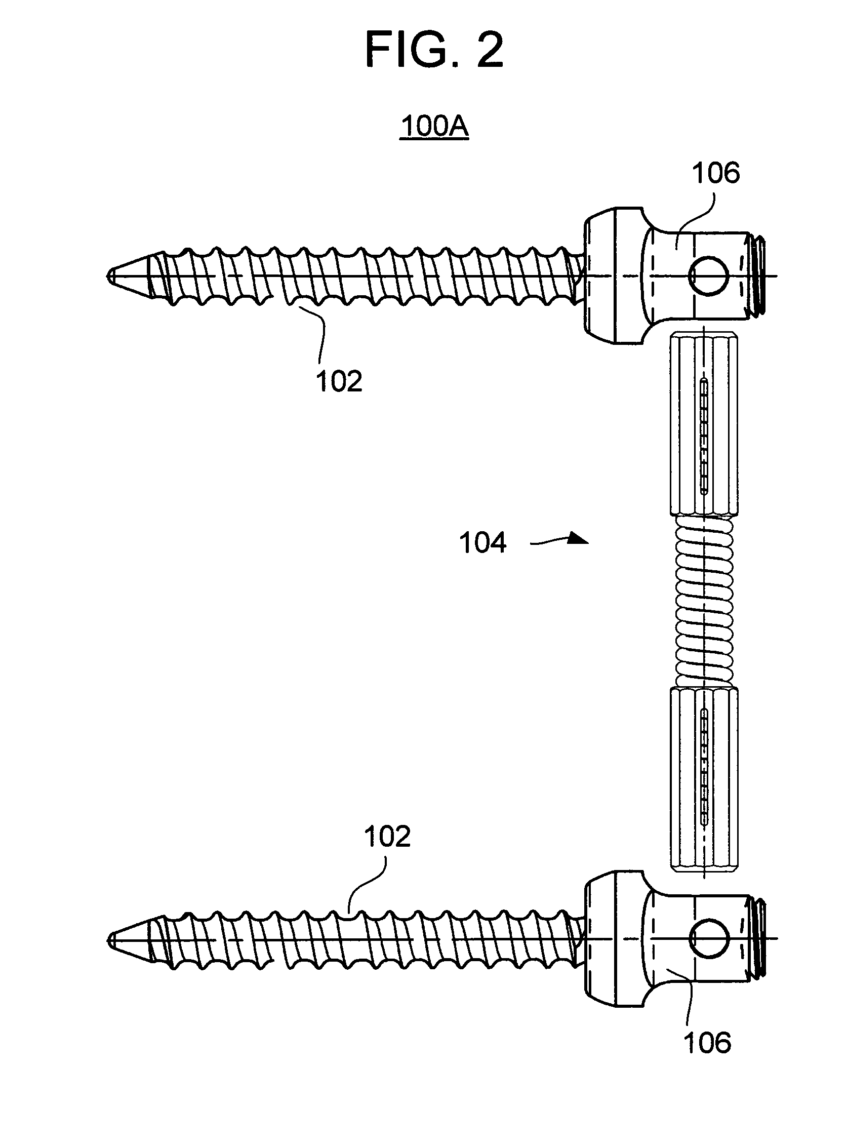
However, this patent is primarily concerned with providing a spinal fixation device that permits “relative longitudinal translational sliding movement along [the] vertical axis” of the spine and neither teaches nor suggests any particular designs of connection units (e.g., rods or plates) that can provide various flexibility characteristics.
Because they are typically very thin to provide suitable flexibility, such prior art rods are prone to mechanical failure and have been known to break after implantation in patients.
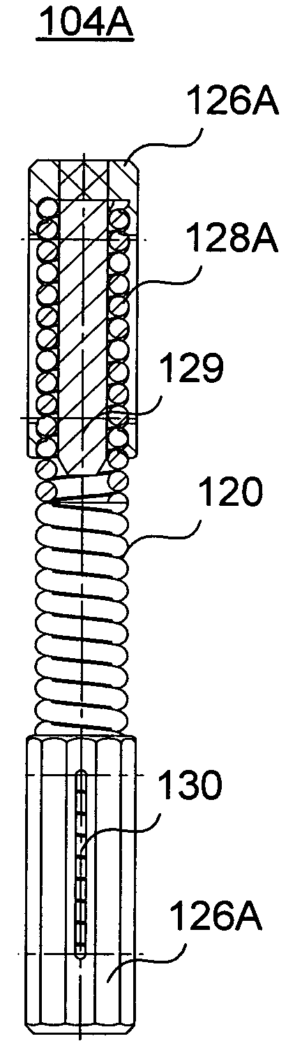
The means by which the springs disclosed in these patents are connected to the vertebrae are disadvantageous because they do not permit ease in changing the length of the spring.
While, for example, U.S. Pat. No. 5,180,393 permits a cascade of spring elements, the resulting spring structure is not in axial alignment.
Further, the length of each individual spring cannot be easily changed during the surgical procedure.
Indeed, such appears to require adjustment during manufacture.
Still further, the disclosed spring structures in these patents do not appear compatible with existing pedicle screws and tulip fixation designs.
Therefore, conventional spinal fixation devices have not provided a comprehensive and balanced solution to the problems associated with curing spinal diseases.
Many of the prior devices are characterized by excessive rigidity, which leads to the problems discussed above while others, though providing some flexibility, are not well-adapted to provide varying degrees of flexibility.
Additionally, existing flexible fixation devices utilize components that are not proven to provide long-term stability and durability, and are cumbersome and overly complex in terms of how they are adjusted and / or attach to the vertebral bones.

Method used


Image

  • Methods and apparatus for vertebral stabilization using sleeved springs
  • Methods and apparatus for vertebral stabilization using sleeved springs
  • Methods and apparatus for vertebral stabilization using sleeved springs

Examples


Embodiment Construction

[0038]FIGS. 1A-B illustrate an embodiment of a spinal stabilizer system 100 in use in accordance with one or more aspects of the present invention. In this embodiment, the system 100 includes two stabilizing elements 100A, 100B (also referred to as dynamic stabilizers) that are designed for single level spinal stabilization, preferably from the posterior of the spine. The posterior stabilizer system 100 is preferably used at the early to moderate stages of the spinal disc degeneration disease process to inhibit posterior disc, vertebral foramen, and inferior vertebral notch collapse with the minimal (semi-constrained) restriction of the vertebral body biological range of motion.

[0039]It is understood that the use of the various embodiments of the invention discussed herein has been directed to a specific application of stabilizing the spine; however, other applications are contemplated without departing from the scope of the invention. Indeed, any application in which a spring eleme...


PUM


Abstract

A stabilization element for implantation in a patient includes: a spring element including a plurality of helical coils terminating at first and second ends; and at least one sleeve including at least one bore sized and shaped to slide or thread onto the helical coils of the spring element, the at least one sleeve being operable to engage a tulip of a bone anchor.

Description

CROSS REFERENCE TO RELATED APPLICATIONS[0001]This application claims the benefit of U.S. Provisional Patent Application No. 60 / 658,365, filed Mar. 3, 2005, the entire disclosure of which is hereby incorporated by reference.BACKGROUND OF THE INVENTION[0002]The present invention is directed to vertebral stabilization of a spine using springs.[0003]Back pain is one of the most common and often debilitating conditions affecting millions of people in all walks of life. Today, it is estimated that over ten million people in the United States alone suffer from persistent back pain. Approximately half of those suffering from persistent back pain are afflicted with chronic disabling pain, which seriously compromises a person's quality of life and is the second most common cause of worker absenteeism. Further, the cost of treating chronic back pain is very high, even though the majority of sufferers do not receive treatment due to health risks, limited treatment options and inadequate therape...

Claims


Application Information

Patent Timeline
Patent Type & Authority Patents(United States)
IPC IPC(8): A61B17/70
CPCA61B17/7074A61B17/7032A61B17/7044A61B17/705A61B17/7028A61B17/2812A61B17/7004A61B17/7007
Inventor ROTHMAN, RICHARD H.ZUBOK, RAFAILKVITNITSKY, MIKHAIL
Owner ALTUS PARTNERS
Why Eureka
Try Eureka