

Amplitude modulated switching voltage regulator
a switching voltage regulator and amplitude modulation technology, applied in the direction of antennas, instruments, electricly long antennas, etc., can solve the problems of limiting the efficiency of this technique and the efficiency of such an arrangement, and achieve the effect of maximizing the efficiency of the am switching voltage regulator, constant shunt current, and minimizing the average value of shunt curren
- Summary
- Abstract
- Description
- Claims
- Application Information
AI Technical Summary
Benefits of technology
Problems solved by technology
Method used
Image

Examples
first embodiment
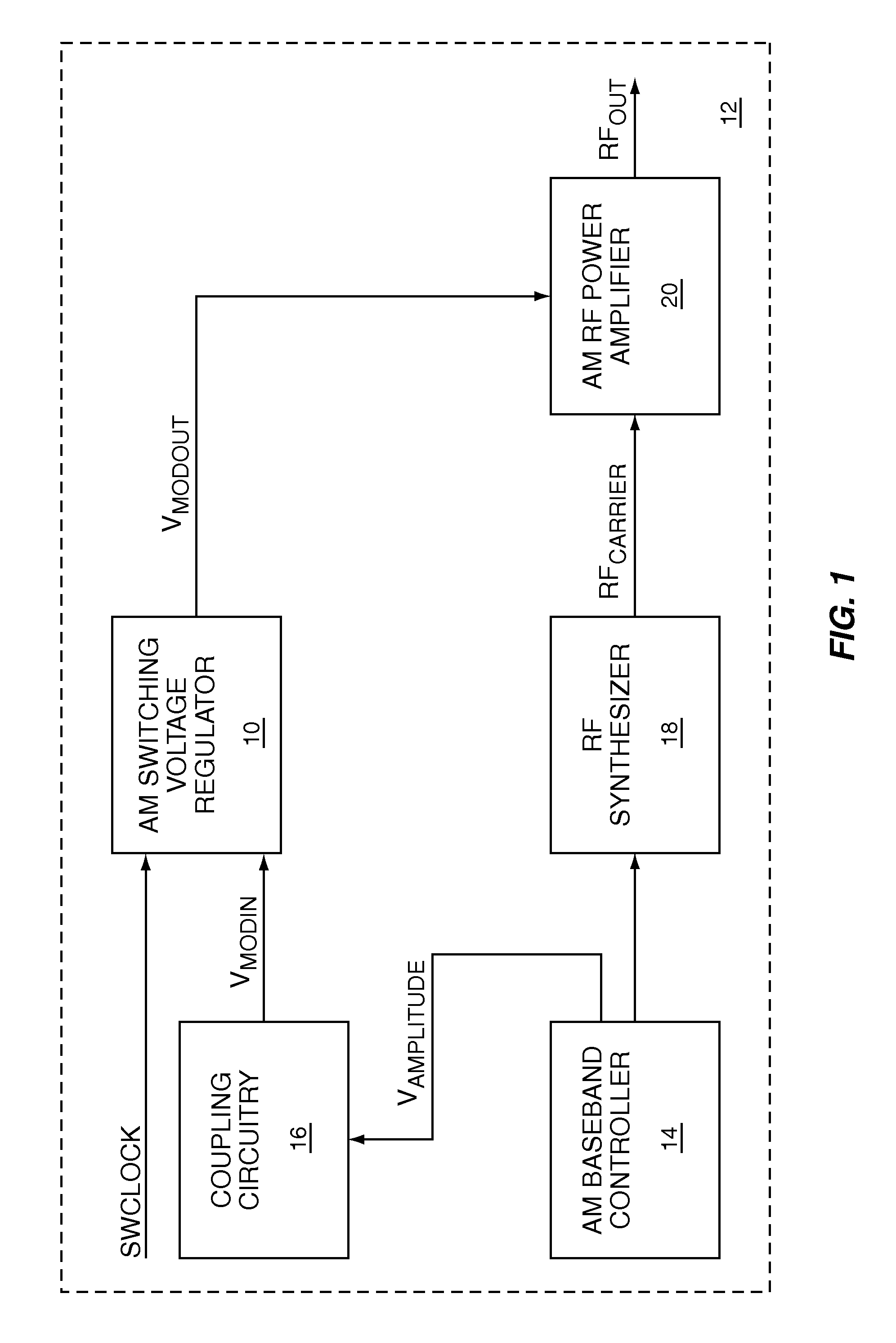
[0026]As shown in FIG. 1, the present invention is a high efficiency AM switching voltage regulator 10 used in an AM transmitter 12. An AM baseband controller 14 encodes data for transmission in an AM modulation signal VAMPLITUDE, which feeds the AM switching voltage regulator 10 through coupling circuitry 16. The AM baseband controller 14 provides the appropriate transmit channel information to an RF synthesizer 18, which generates an RF carrier signal RFCARRIER for an AM RF power amplifier 20. Using the AM modulation signal VAMPLITUDE, the coupling circuitry 16 provides an AM input signal VMODIN to the AM switching voltage regulator 10, which provides a low impedance AM output signal VMODOUT to the AM RF power amplifier 20 based on VMODIN. The AM switching voltage regulator 10 is a high efficiency design using switching power supply technology, which is driven from a switching clock signal SWCLOCK. The AM RF power amplifier 20 amplifies and modulates RFCARRIER to create an AM RF o...
second embodiment
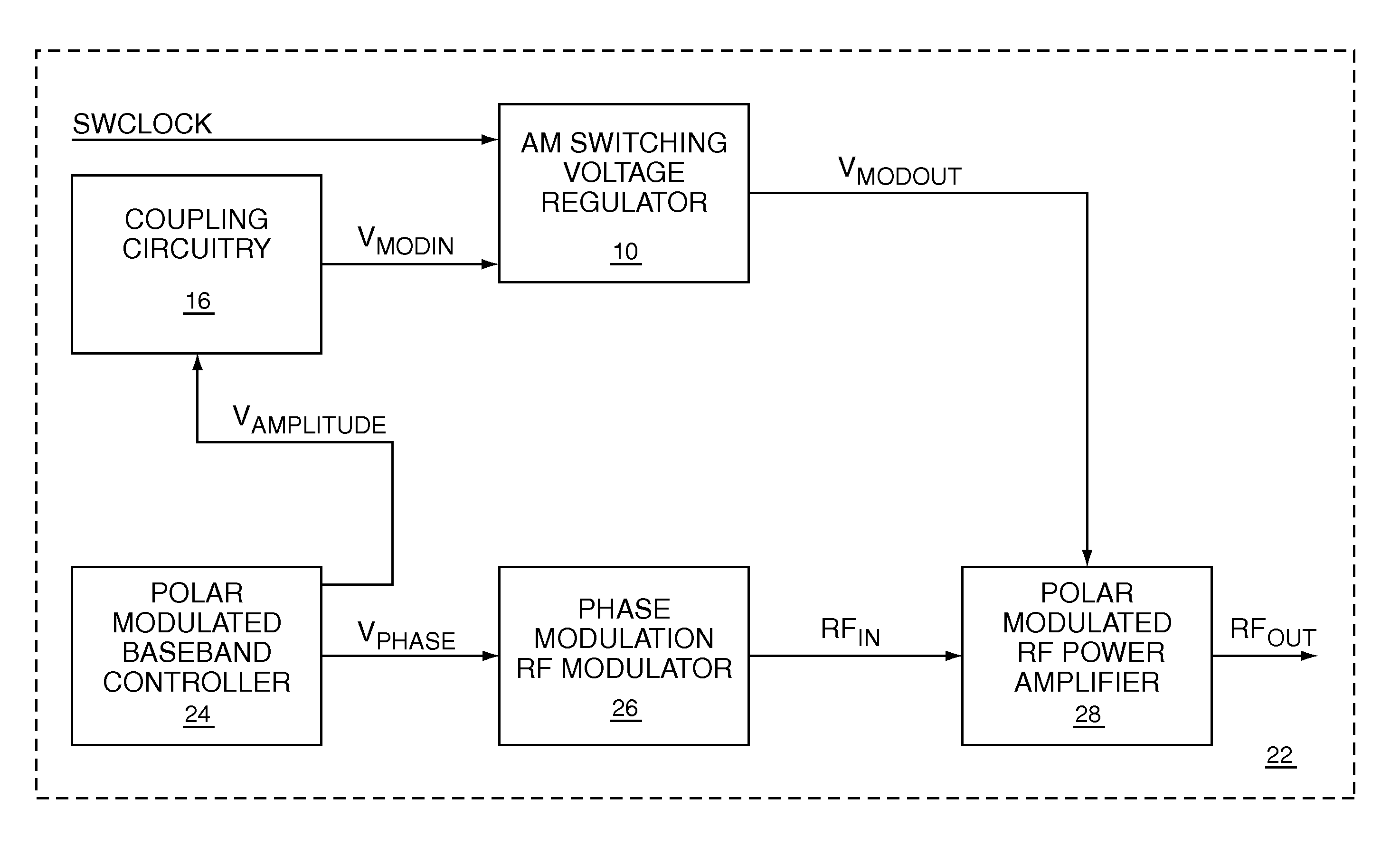
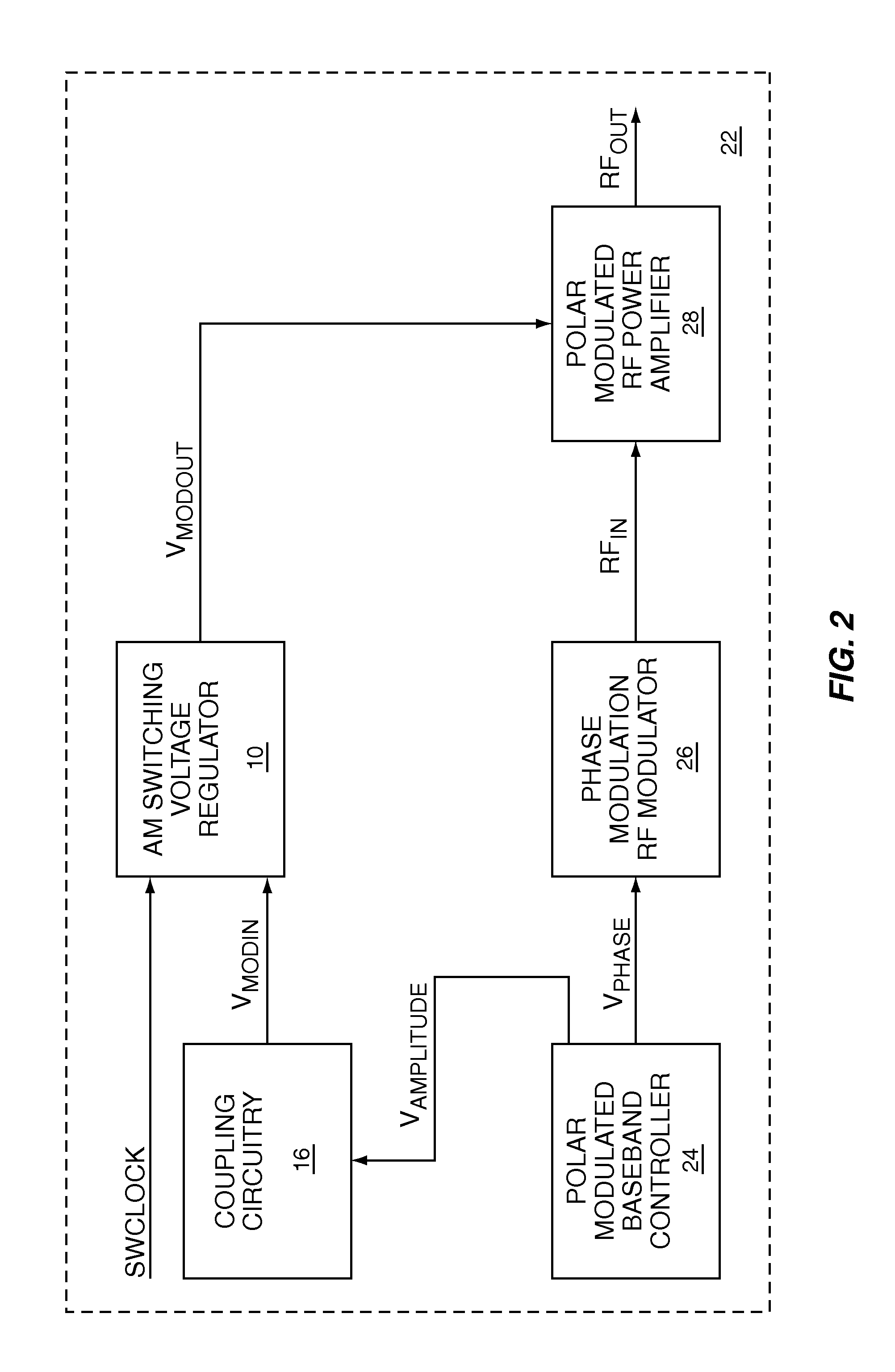
[0027]As shown in FIG. 2, the present invention is a high efficiency AM switching voltage regulator 10 used in a polar modulated transmitter 22. A polar modulated baseband controller 24 encodes data for transmission in an AM modulation signal VAMPLITUDE and a phase modulation signal VPHASE, which feed a polar modulation RF modulator 26 and coupling circuitry 16. The polar modulation RF modulator 26 phase modulates an RF carrier signal to create a phase modulated RF input signal RFIN for a polar modulated RF power amplifier 28. Using the AM modulation signal VAMPLITUDE, the coupling circuitry 16 provides the AM input signal VMODIN to the AM switching voltage regulator 10, which provides the low impedance AM output signal VMODOUT to the polar modulated RF power amplifier 28. The polar modulated RF power amplifier 28 amplifies and amplitude modulates RFIN to create a polar modulated RF output signal RFOUT. The low impedance AM output signal VMODOUT provides an envelope supply voltage t...
PUM
 Abstract
Description
Claims
Application Information