
Extreme chirped/stretched pulsed amplification and laser

a pulsed amplification and laser technology, applied in the field of lasers, can solve the problems of short energy storage life of semiconductor gain medium, insufficient high-power generation of semiconductor optical amplifier, and insufficient energy extraction efficiency of semiconductor gain medium compared with other gain mediums with a longer energy storage lifetime. achieve the effect of efficiently external compression and high power

Inactive Publication Date: 2009-07-07
UNIV OF CENT FLORIDA RES FOUND INC
View PDF24 Cites 10 Cited by
  • Summary
  • Abstract
  • Description
  • Claims
  • Application Information

AI Technical Summary

Benefits of technology

"The present invention provides methods, devices, and systems for generating ultrashort optical pulses with high power. The invention involves stretching the time duration of pulses passing through a gain media to suppress self-phase modulation, and compressing them prior to saturation to increase the optical power. The invention also includes a method of generating ultra-short optical pulses with high power by increasing the temporal duration of the pulses and amplifying them. The invention can be implemented using a mode-locked laser source and a semiconductor optical amplifier. The invention can also include modulating the optical pulse to further shorten it. The technical effects of the invention include generating high-power optical pulses with increased optical power and efficiency."

Problems solved by technology

Semiconductor gain mediums have a short energy storage lifetime which makes energy extraction from the semiconductor gain medium less efficient compared with other gain mediums that have a longer energy storage lifetime.
It is well known that semiconductor optical amplifiers are not a proper optical amplifier for high power generation.
Previously, external cavity mode-locked semiconductor laser oscillators did not use dispersion management schemes that provide breathing mode operation.
Short pulses below ˜1 ps. bleach the saturable absorber much easier, but such short pulses would initiate different ultra-fast dynamic processes in gain media which are detrimental for the laser operation—the gain would be decreased and the pulse would be strongly nonlinearly chirped.
The nonlinear chirp is very difficult to compensate and generate in the end ultrashort pulses

Method used


Image

  • Extreme chirped/stretched pulsed amplification and laser
  • Extreme chirped/stretched pulsed amplification and laser
  • Extreme chirped/stretched pulsed amplification and laser

Examples


Embodiment Construction

[0094]Before explaining the disclosed embodiments of the present invention in detail it is to be understood that the invention is not limited in its application to the details of the particular arrangements shown since the invention is capable of other embodiments. Also, the terminology used herein is for the purpose of description and not of limitation.

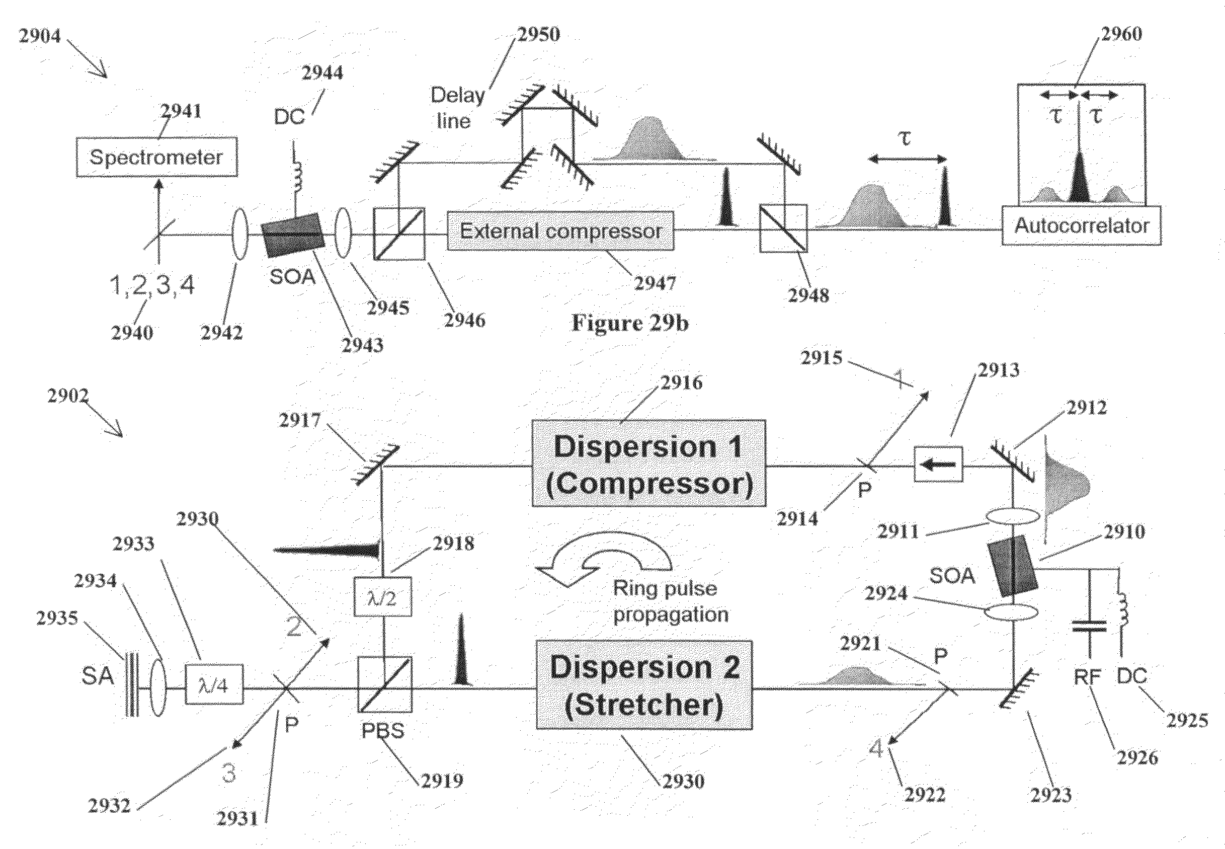
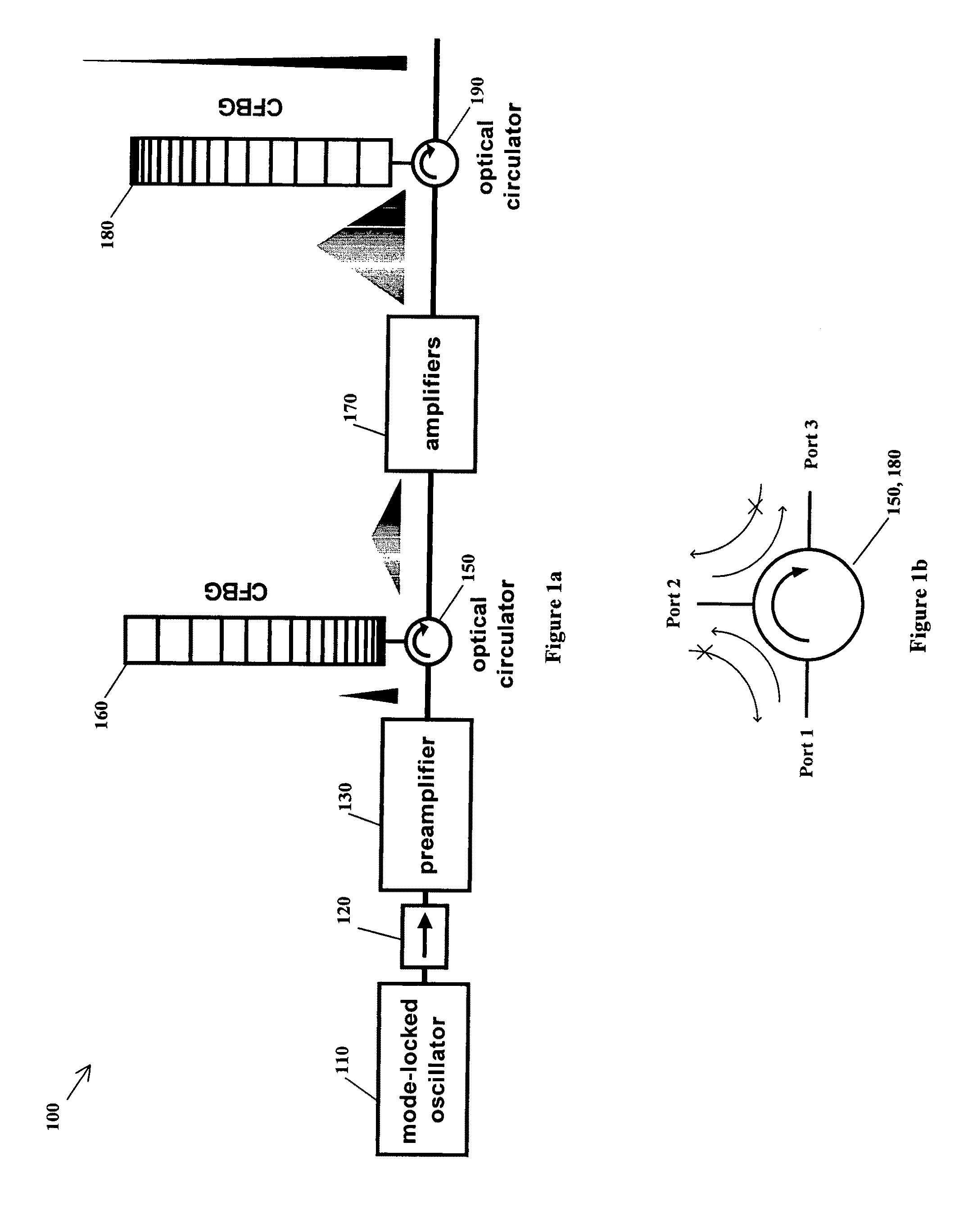
[0095]FIG. 1a shows a setup of a preferred embodiment of the extreme chirped pulsed amplifier (X-CPA) invention, 100. Mode-locked laser 110 with semiconductor gain medium is used as an oscillator. The repetition rate of the oscillator is adjustable. Optical isolator (OI) 120, 140 allows the optical pulse to travel in the direction of the arrow and blocks the optical pulse in the reverse direction. Preamplifier 130 is a semiconductor optical amplifier that (a) compensates for losses from the first optical isolator 120, the optical circulator 150, and the chirped Bragg grating 160; (b) develops more power to saturate the amplifier 170;...


PUM


Abstract

Methods, devices and systems for generating ultrashort optical linear chirped pulses with very high power by amplifying the pulses so that their temporal duration is longer than the storage time of the amplifying medium. The additional gain factor is related to the ratio of the storage time to the stretched pulse. A preferred embodiment connects a mode locked laser source that generates optical pulses whose duration is stretched with a chirped fiber Bragg grating. Embodiments include methods, devices and systems causing an extreme chirped pulse amplifier (XCPA) effect in an oscillator.

Description

[0001]This is a Divisional of application Ser. No. 11 / 445,565 filed Jun. 2, 2006 which is a Divisional of application Ser. No. 10 / 828,965 filed Apr. 21, 2004, now U.S. Pat. No. 7,095,772 which claims priority of U.S. Provisional Application 60 / 472,383 filed May 21, 2003.FIELD OF USE[0002]This invention relates to lasers, in particular to methods, devices and systems for generating ultra-short optical pulses with very high power by stretching optical pulses to durations longer than the energy storage time of an optical amplifier, and for deployment of an extreme chirped pulse amplification (XCPA) effect in an laser oscillator and an external amplification.BACKGROUND AND PRIOR ART[0003]Semiconductor gain mediums have a short energy storage lifetime which makes energy extraction from the semiconductor gain medium less efficient compared with other gain mediums that have a longer energy storage lifetime. That is, a semiconductor optical amplifier is easily saturated and, after reaching ...

Claims


Application Information

Patent Timeline
Patent Type & Authority Patents(United States)
IPC IPC(8): H01S3/00H01S3/04H01S3/08H01S3/10H04B10/12
CPCH01S5/50H01S3/0057H01S5/065H01S5/0657H01S2301/02H01S5/5027H01S5/141
Inventor DELFYETT, PETERKIM, KYUNGBUMRESAN, BOJAN
Owner UNIV OF CENT FLORIDA RES FOUND INC
Learn More