
Control apparatus and method for internal combustion engine

a control apparatus and internal combustion engine technology, applied in mechanical equipment, electric control, machines/engines, etc., can solve the problem of not taking fact into account, and achieve the effect of high accuracy, fast, and constant high efficiency of exhaust control and catalytic conversion

Inactive Publication Date: 2009-07-14
HITACHI AUTOMOTIVE SYST LTD
View PDF16 Cites 13 Cited by
  • Summary
  • Abstract
  • Description
  • Claims
  • Application Information

AI Technical Summary

Benefits of technology

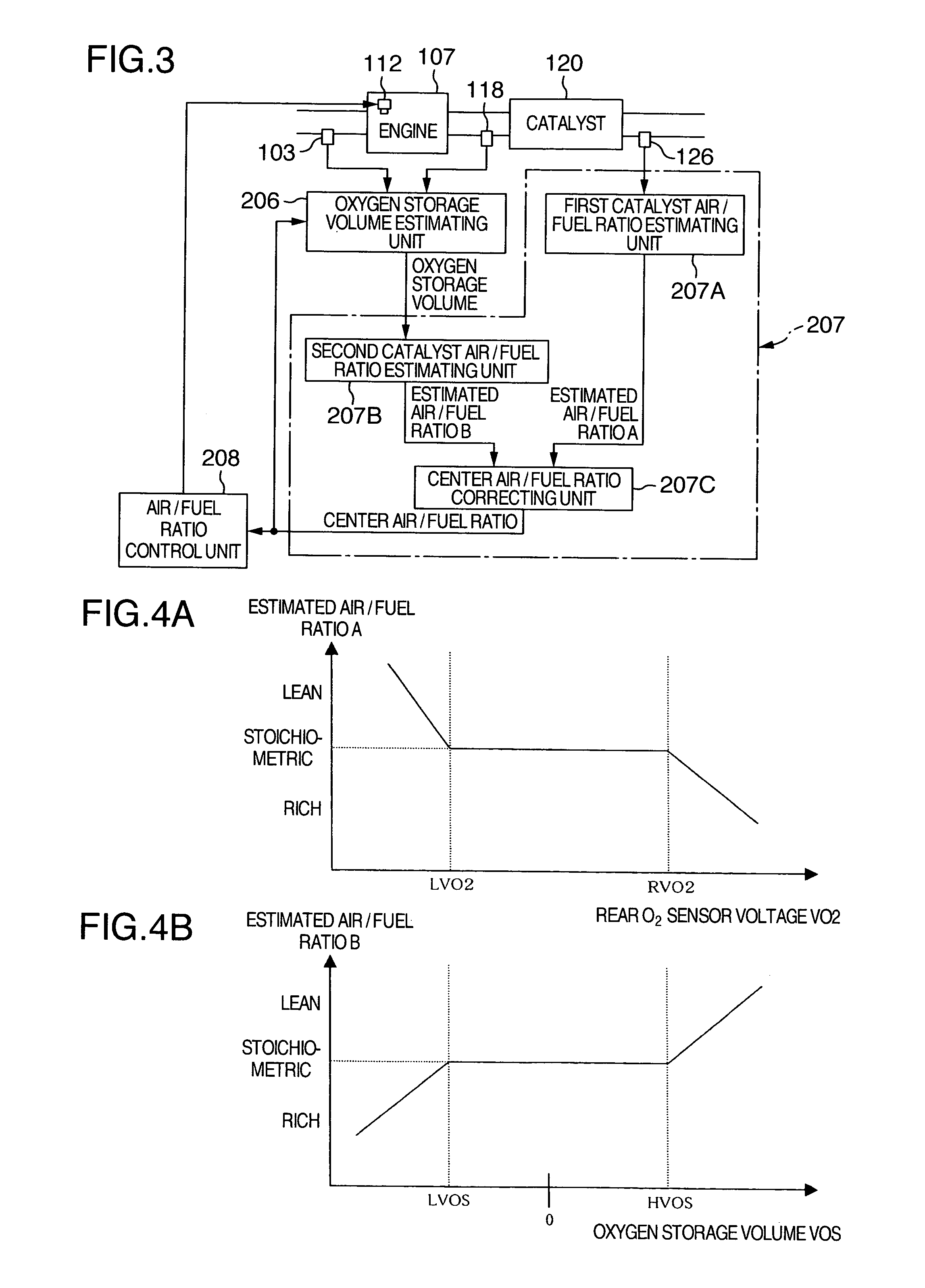
The present invention provides a control apparatus for an internal combustion engine that improves the accuracy of estimating the oxygen storage volume of a catalyst and the efficiency of catalytic conversion. This is achieved by using a front air / fuel ratio sensor to detect the air / fuel ratio, and a center air / fuel ratio correcting unit to estimate the center air / fuel ratio based on the output of a rear O2 sensor. The center air / fuel ratio correcting unit takes into account the variation in the air / fuel ratio sensor and the deterioration of the catalyst. The control apparatus also includes an air / fuel ratio control unit to control the air / fuel ratio so that the air / fuel ratio detected by the front air / fuel ratio sensor agrees with a target air / fuel ratio. This results in improved accuracy of catalyst deterioration determination and the efficiency of catalytic conversion.

Problems solved by technology

However, this fact was not taken into sufficient consideration in the prior art.

Method used


Image

  • Control apparatus and method for internal combustion engine
  • Control apparatus and method for internal combustion engine
  • Control apparatus and method for internal combustion engine

Examples


Embodiment Construction

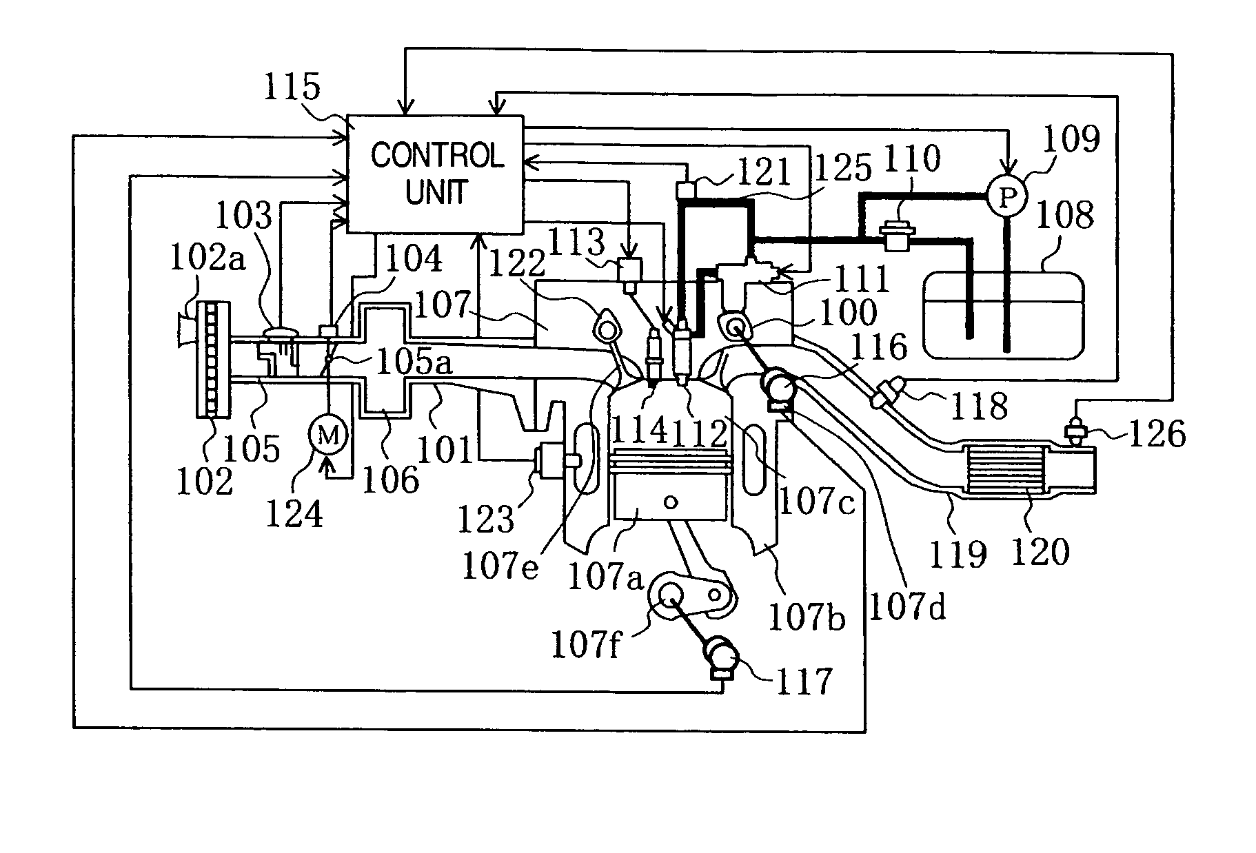
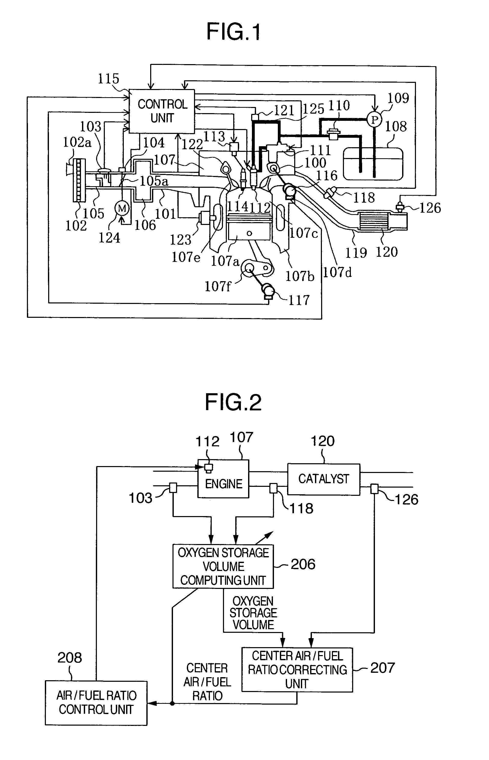
[0044]Embodiments of a control apparatus for an internal combustion engine of the present invention will be described with reference to the drawings.

[0045]FIG. 1 shows a general configuration of a control system for cylinder injection type internal combustion engine to which the control apparatus for an internal combustion engine according to the present invention.

[0046]An engine 107 has a plurality of combustion chambers, which are demarcated by a cylinder block 107B and pistons 107A.

[0047]Air drawn into a combustion chamber 107C of the engine 107 is taken from an inlet 102A of an air cleaner 102, and the air passes through an airflow sensor 103, which is one of the running condition measuring unit of the internal combustion engine, then goes through a throttle body 105, which contains an electric control throttle valve 105A for controlling an intake air flow rate, and enters a collector 106. The electric control throttle valve is driven and has its opening set by an electric motor...


PUM


Abstract

A control apparatus for an internal combustion engine has an oxygen storage volume computing unit for computing an oxygen storage volume of a catalyst by using a real air / fuel ratio detected by an air / fuel ratio sensor installed on the upstream side of a catalyst, a center air / fuel ratio representing a stoichiometric air / fuel ratio and an estimated air flow volume or detecting a flow rate of air flowing into the catalyst. A center air / fuel ratio correcting unit for correcting a center air / fuel ratio based on output of a rear air / fuel ratio sensor provided on the downstream side of the catalyst, and an oxygen storage volume computed by an oxygen storage volume computing unit, and the oxygen storage volume computing unit computes an oxygen storage volume by using a center air / fuel ratio corrected by the center air / fuel ratio correcting unit.

Description

BACKGROUND OF THE INVENTION[0001]The present invention relates to a control apparatus and a control method for an internal combustion engine, and more particularly to a control apparatus and a control method for an internal combustion engine, the control apparatus including means for controlling an air / fuel ratio and means for determining deterioration of the catalyst based on an oxygen storage volume of the catalyst.[0002]Among control units for controlling the air / fuel ratio of an internal combustion engine, there is a type that computes an absolute volume of oxygen stored in a catalyst based on output of an air / fuel ratio sensor (an O2 sensor or a linear air / fuel ratio sensor) for detecting exhaust components installed on the upstream side of the catalyst in the exhaust passage of the engine and also based on output of an airflow sensor for measuring a volume of air drawn into the combustion chamber of the engine, and that controls the air / fuel ratio based on an estimated oxygen ...

Claims


Application Information

Patent Timeline
Patent Type & Authority Patents(United States)
IPC IPC(8): F01N3/00F01N3/20F02D41/14F02D41/22F02D41/34F02D45/00
CPCF01N11/007F02D41/1441F02D41/0295F01N3/0864F01N2560/025F01N2560/14Y02T10/22F02D41/18F02D2200/0816Y02T10/47Y02T10/12Y02T10/40
Inventor IIHOSHI, YOICHIYAMAUCHI, SHINHORI, TOSHIOKURASHIMA, YOSHIKUNI
Owner HITACHI AUTOMOTIVE SYST LTD
Learn More