Method and device for controlling the injection of reducing agent

a technology of reducing agent and injection method, which is applied in the direction of braking system, process and machine control, instruments, etc., can solve the problem of incorrect proportioning of reducing agent, and achieve the effect of easy and reliable control

Inactive Publication Date: 2009-07-14
SCANIA CV AB
View PDF15 Cites 23 Cited by
  • Summary
  • Abstract
  • Description
  • Claims
  • Application Information

AI Technical Summary

Benefits of technology

[0006]The object of the present invention is to provide a method which enables easy and reliable control of the injection of reducing agent upstream from a catalyst in an exhaust line from a combustion engine so that amounts of reducing agent which are appropriate to prevailing operating conditions can be injected.SUMMARY OF THE INVENTION
[0013]The solution according to the invention makes it possible easily and reliably to control the injection of reducing agent upstream from a catalyst in an exhaust line from a combustion engine so that suitable amounts of reducing agent can be injected, based on prevailing operating conditions, for achieving a desired conversion of the exhaust gas substance concerned. Taking the current reducing substance accumulation in the catalyst into account makes it possible to control the proportioning of reducing agent with good accuracy so that the desired conversion of the exhaust gas substance is accomplished while at the same time the amount of unconsumed reducing substance which accompanies the exhaust gases leaving the catalyst and thereby reaches the environment is limited. It thus becomes possible to minimise the consumption of reducing agent and the relating costs while at the same time preventing or at least minimising undesired release of reducing agent to the environment. The computation model used need only be adapted to the catalyst and is therefore independent of the design of the combustion engine connected to the catalyst. Using a computation model which is only tied to the catalyst and not to the combustion engine results in a very flexible method which, when adapted to a specific catalyst, can be used for that catalyst together with any desired combustion engine. It is also possible to use a scalable computation model which can easily be adapted to the dimensions of the catalyst.
[0014]According to an embodiment of the method according to the invention, a limitation factor is calculated, which limitation factor has a value based on an estimate of the current risk that the reducing substance content of the exhaust gases leaving the catalyst might exceed a predetermined limit value, whereby this limitation factor is taken into account in calculating the accumulation setpoint value in such a way that the accumulation setpoint value decreases in response to increasing risk that the reducing substance content of the exhaust gases leaving the catalyst might exceed the predetermined limit value. It thus becomes possible to eliminate or at least minimise the risk that undesired amounts of unconsumed reducing substance might accompany the exhaust gases leaving the catalyst and thereby reach the environment.

Problems solved by technology

A further disadvantage of the known solution is that, despite dynamic compensations, operating conditions for which the tables do not cater can occur, which may lead to incorrect proportioning of reducing agent.

Method used


Image

  • Method and device for controlling the injection of reducing agent
  • Method and device for controlling the injection of reducing agent
  • Method and device for controlling the injection of reducing agent

Examples


first embodiment

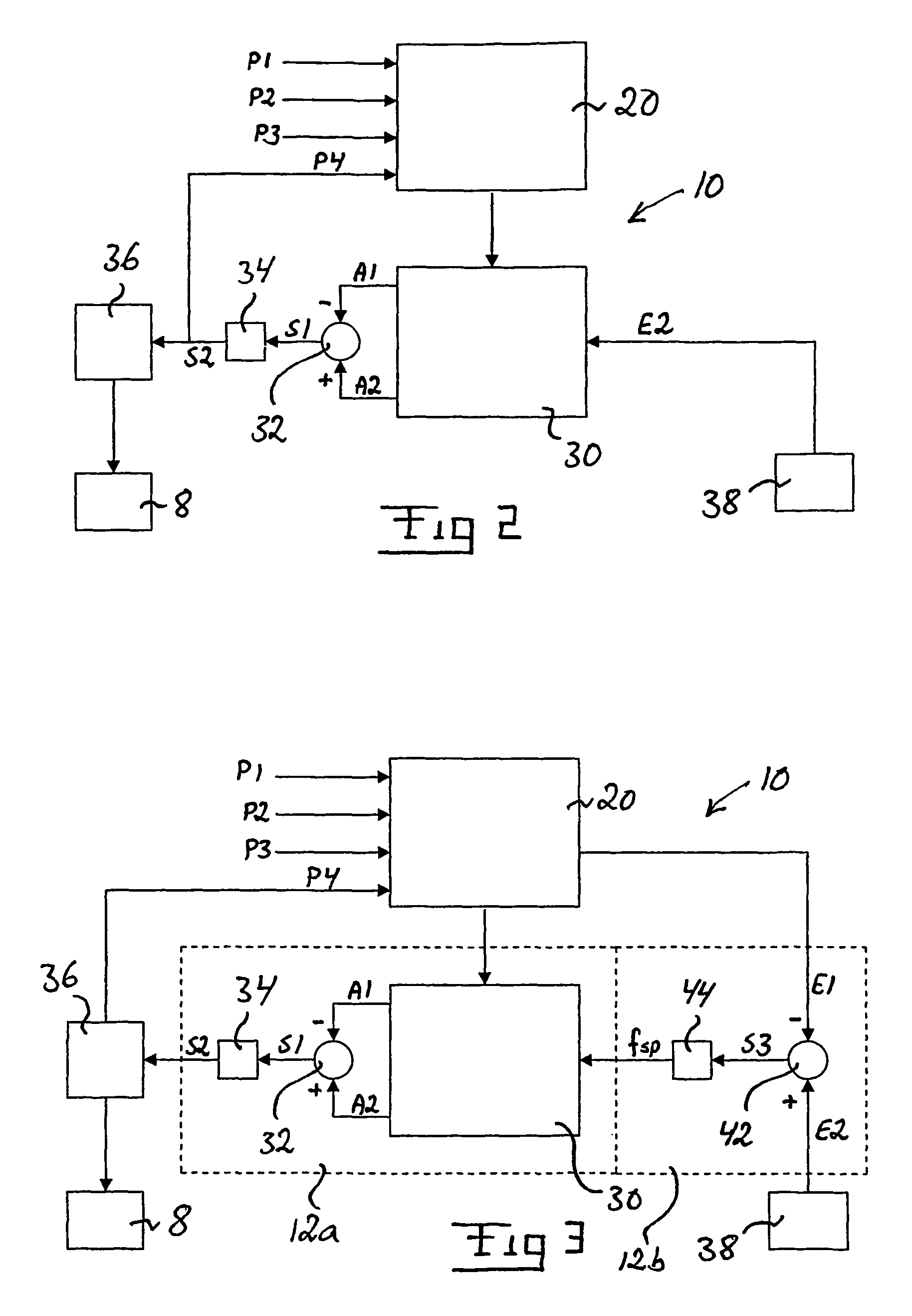
[0036]FIG. 2 illustrates a device 10 according to the invention. The device 10 comprises a first calculation means 20 adapted to determining continuously, by use of a computation model, the current state of the catalyst, taking into account the expected reactions in the catalyst under prevailing operating conditions. The computation model takes into account the expected exothermal and endothermal reactions in the catalyst 4 under prevailing operating conditions and calculates inter alia the accumulation of the reducing substance concerned in different parts of the catalyst, and the conversion of the exhaust gas substance concerned which takes place in different parts of the catalyst. The computation model may be of any desired design provided that it produces with the desired accuracy a correct value for the accumulation of the reducing substance and the conversion of the exhaust gas substance in the catalyst. An example of a computation model suitable in the context is described be...

second embodiment

[0040]FIG. 3 illustrates a device 10 according to the invention. The components which appear both in the embodiment described above with reference to FIG. 2 and in the embodiment according to FIG. 3 are denoted by the same reference notations. In the embodiment according to FIG. 3, the device 10 likewise comprises means for determining by calculation or measurement an emission actual value E1 representative of the current exhaust gas substance content of the exhaust gases leaving the catalyst 4. In cases where the emission actual value E1 is determined by calculation, this is preferably done in the first computation means 20 by using the abovementioned computation model or in a separate computation means on the basis of information from that computation model. In cases where the emission actual value E1 is determined by measurement, this is done by a measuring means arranged in the exhaust line downstream from the catalyst 4.

[0041]In the embodiment according to FIG. 3, the second co...


PUM


Abstract

The invention relates to a method and device (10) for controlling the injection of reducing agent upstream from a catalyst (4) in an exhaust line (2) from a combustion engine. According to the invention, the injection of reducing agent in the exhaust line is controlled on the basis of result of comparison between a calculated accumulation actual value (A1) and a calculated accumulation setpoint value (A2). The invention also relates to a computer program comprising program code for implementing said method, a computer program product comprising a medium which is readable by an electronic control unit and has stored on it a computer program intended to cause an electronic control unit to implement said method, and an electronic control unit.

Description

CROSS REFERENCE TO RELATED APPLICATION[0001]The present application is a 35 U.S.C. §§ 371 national phase conversion of PCT / SE2004 / 001984, filed 22 Dec. 2004, which claims priority of Swedish Application No. 0400104-6, filed 20 Jan. 2004. The PCT International Application was published in the English language.FIELD OF THE INVENTION, AND STATE OF THE ART[0002]The present invention relates to a method and a device for controlling the injection of reducing agent upstream from a catalyst in an exhaust line from a combustion engine. The invention also relates to a computer program comprising program codes for implementation of said method, a computer program product comprising a medium which is readable by an electronic control unit and has stored on it a computer program intended to cause an electronic unit to implement said method, and an electronic control unit.[0003]To meet prevailing exhaust cleaning requirements, today's motor vehicles are usually provided with a catalyst in the exh...

Claims


Application Information

Patent Timeline
Patent Type & Authority Patents(United States)
IPC IPC(8): F01N3/00F01N3/20F01N9/00
CPCF01N3/208F01N9/005F01N2610/02Y02T10/24F01N2900/1402F01N2900/1622F01N2900/0406Y02T10/12
Inventor WESTERBERG, BJORN
Owner SCANIA CV AB
Why Eureka
Try Eureka