Alumina member and manufacturing method thereof

a technology of alumina members and manufacturing methods, applied in the field of alumina members, can solve problems such as the reduction of the strength of alumina members

Active Publication Date: 2009-07-21
NGK INSULATORS LTD
View PDF16 Cites 16 Cited by
  • Summary
  • Abstract
  • Description
  • Claims
  • Application Information

AI Technical Summary

Benefits of technology

[0009]According to the alumina member as described above, the power-supplied member and the terminal are firmly bonded to each other. Moreover, the base of the sintered body containing alumina and the bonding member are approximate to each other in coefficient of thermal expansion. Accordingly, a crack which may be caused by embedding the bonding member in the base can be prevented from occurring. Therefore, strength of the alumina member can be enhanced by embedding the bonding member therein, and the crack which may be caused by the embedding can also be prevented from occurring. Hence, the strength of the alumina member can be enhanced. In addition, the melting point of the bonding member is higher than the baking temperature of the sintered body, and accordingly, in a manufacturing process of the alumina member, the bonding member can be prevented from being deformed, and a component of the bonding member can be prevented from being diffused into the base. Hence, a malfunction does not occur owing to the embedding of the bonding member.
[0021]For example, at least a part of the compact contains at least one of either carbon powder or a binder serving as a carbon source, thus making it possible to perform the baking in the state where carbon is present in the periphery of the bonding member.

Problems solved by technology

Moreover, there has been a possibility that the formation of the hole, and so on, may bring a strength reduction of the alumina member.

Method used


Image

  • Alumina member and manufacturing method thereof
  • Alumina member and manufacturing method thereof
  • Alumina member and manufacturing method thereof

Examples


examples

[0087]Next, the present invention will be described more in detail by examples; however, the present invention is not limited to the following examples at all.

examples 1 to 6

, Comparative Examples 1 to 3

[0088]As ceramics material powder, alumina powder with a purity of 99.9 wt % and a mean particle diameter of 0.5 μm was prepared. To the alumina powder, water, the dispersant, and polyvinyl alcohol as the binder were added, and were mixed by a trammel, and the slurry was thus prepared. The obtained slurry was sprayed and dried by using a spray dryer, and the alumina granulated powder was prepared. The prepared alumina granulated powder was filled into the die mold, and was pressurized with 200 kg / cm2, and nine compacts were fabricated.

[0089]The obtained alumina compacts were set in a carbon-made sheath, were baked by the hot pressing, and the alumina sintered bodies were obtained. Specifically, the compacts were baked in a nitrogen-pressurized atmosphere (nitrogen: 150 kPa) while being pressurized with 100 kg / cm2. Moreover, the baking was performed while raising the temperature from room temperature to 1600° C. at a rate of 100° C. per hour and maintaini...

examples 7 to 9

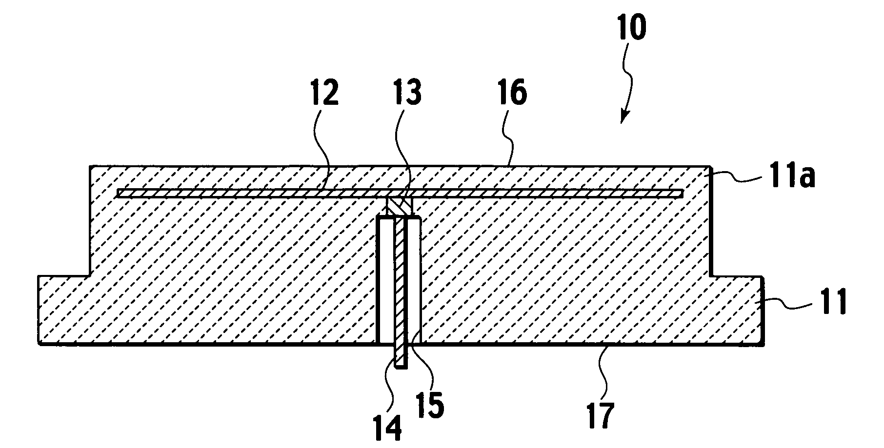
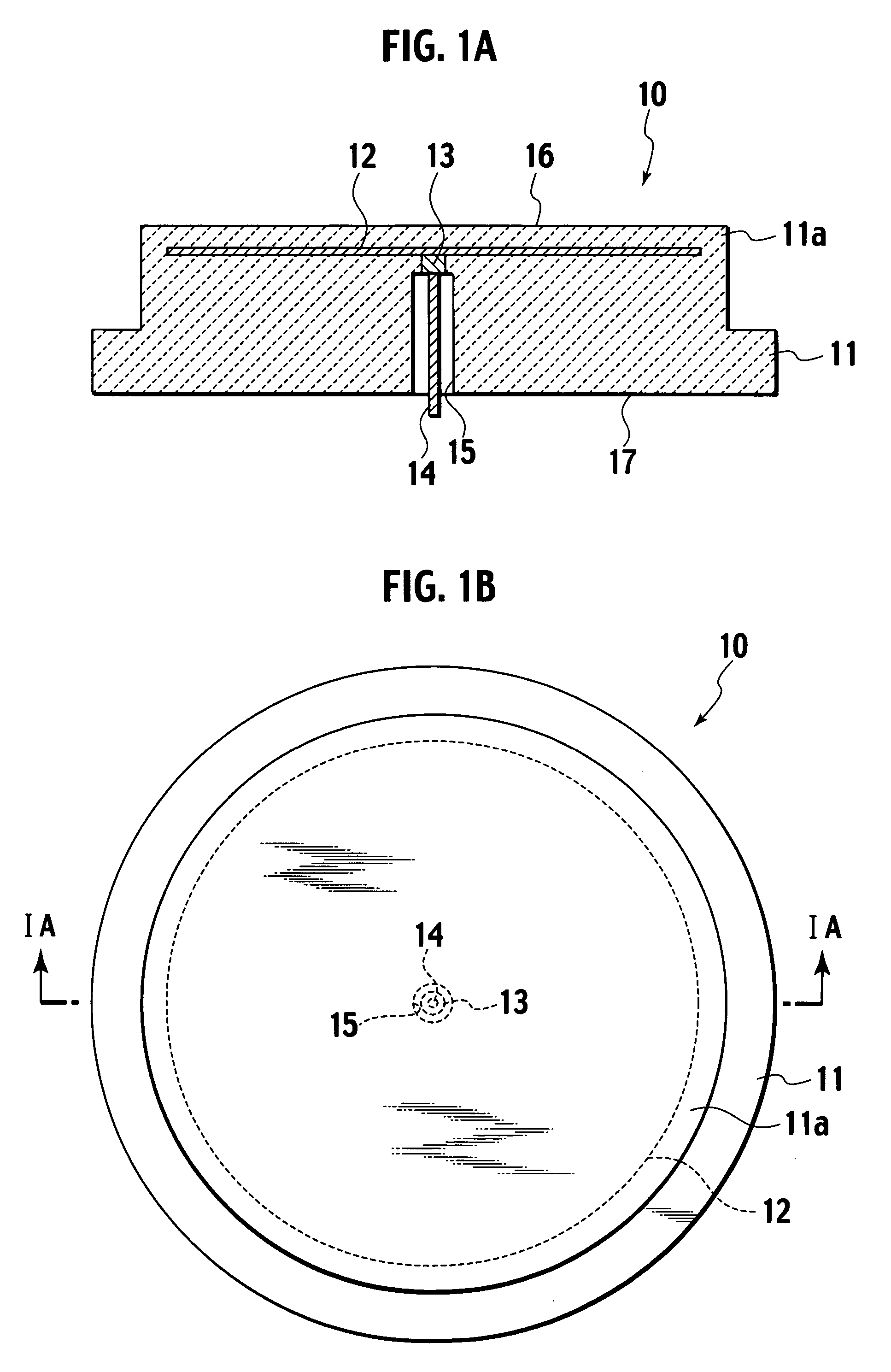
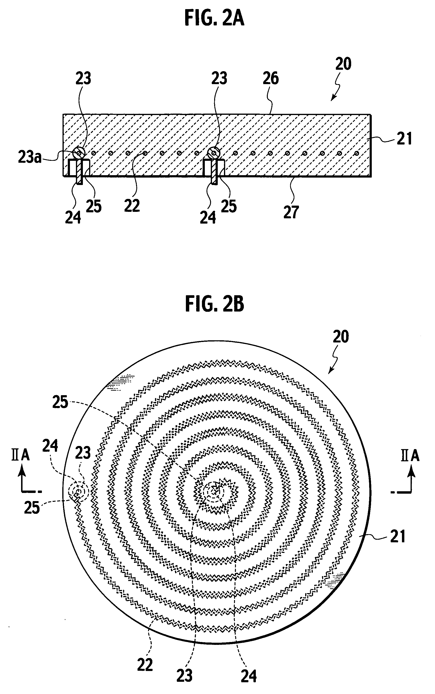
[0104]In Example 7, an alumina member in which the niobium-made bonding member was embedded was fabricated in a similar way to Example 1 except that polyvinyl alcohol as the binder was not added thereto. In Example 8, an alumina member on which the carbon tape was coated and in which the niobium-made bonding member was embedded was fabricated in a similar way to Example 7 except that the tape-like carbon (carbon tape) with a thickness of approximately 0.1 mm was pasted to the bonding member, and that the bonding member was coated with carbon. In Example 9, an alumina member in which the platinum-made bonding member was embedded was fabricated in a similar way to Example 6 except that polyvinyl alcohol as the binder was not added thereto.

[0105]For each of the alumina members of Examples 7 and 9, in a similar way to Example 1, it was confirmed whether or not the crack occurred and the component of the bonding member was diffused into the base of the alumina sintered body, and the punc...


PUM

PropertyMeasurementUnit
weightaaaaaaaaaa
densityaaaaaaaaaa
densityaaaaaaaaaa

Abstract

An electrostatic chuck includes a base of a sintered body containing alumina, an electrode as a power-supplied member embedded in the base and supplied with electric power, a bonding member embedded in the base and bonded to the electrode, in which a difference in coefficient of thermal expansion from the sintered body is 2×10⁻⁶ / K or less, and a melting point is higher than baking temperature of the sintered body, and a terminal bonded to the electrode through the bonding member.

Description

CROSS REFERENCE TO RELATED APPLICATIONS[0001]This application is based upon and claims the benefit of priority from prior Japanese Patent Application No. P2004-361882, filed on Dec. 14, 2004, and No. P2005-256484, filed on Sep. 5, 2005; the entire contents of which are incorporated herein by reference.BACKGROUND OF THE INVENTION[0002]1. Field of the Invention[0003]The present invention relates to an alumina member suitable for an electrostatic chuck and a heater and to a manufacturing method thereof.[0004]2. Description of the Related Art[0005]Heretofore, in a semiconductor manufacturing process, there has been used an alumina member, such as an electrostatic chuck in which an electrode is embedded in an alumina sintered body, and a heater in which a resistance heating element is embedded in such an alumina sintered body. To each the electrode and the resistance heating element, a terminal for connecting a power supply line thereto is bonded by brazing or the like. Moreover, in the ...

Claims


Application Information

Patent Timeline
Patent Type & Authority Patents(United States)
IPC IPC(8): H05B3/68C23C16/00
CPCB23K35/24H01L21/67103H01L21/6833H01L21/68757C04B35/645C04B37/025C04B37/026B23K35/32Y10T29/49087C04B2235/6562C04B2235/6567C04B2235/658C04B2237/086C04B2237/122C04B2237/123C04B2237/125C04B2237/343C04B2237/403C04B2237/62C04B2237/704C04B2237/706C04B2237/72C04B2237/76C04B2237/84H01L21/68
Inventor MORI, YUTAKAMATSUDA, HIROTONOBORI, KAZUHIRO
Owner NGK INSULATORS LTD
Why Eureka
Try Eureka