

A-V dialysis graft
- Summary
- Abstract
- Description
- Claims
- Application Information
AI Technical Summary
Benefits of technology
Problems solved by technology
Method used
Image

Examples
second embodiment
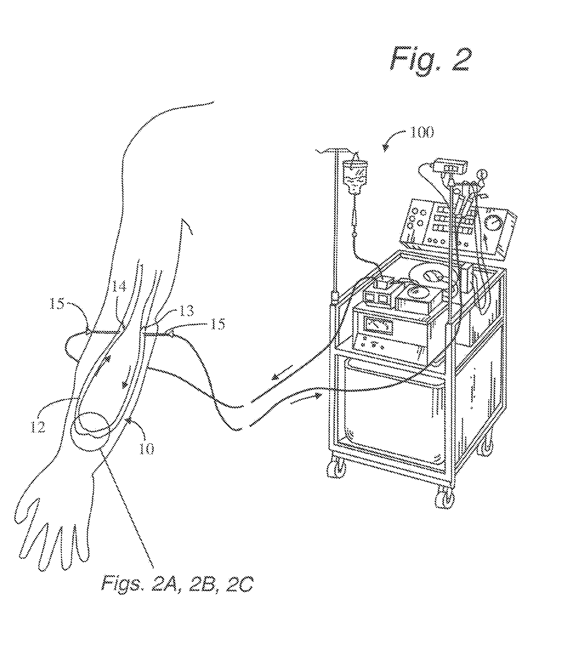
[0037]In FIG. 2C, the improved graft construction 10 is detailed. Here, the polymer tubing 12 is constructed to have a substantially constant diameter throughout. The stenosis 16 is provided by an annular balloon 230 disposed about the inner circumference of the polymer tubing 12. The annular balloon 230 provides an opportunity to vary the stenosis 16. It is to be understood that structures other than an annular balloon could be used to provide a variable stenosis.
first embodiment
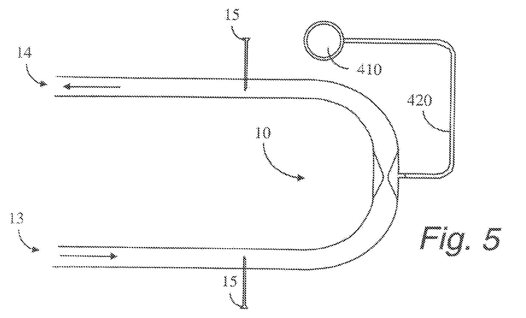
[0038]The configuration of the annular stenosis balloon 230 may range from abrupt to smoothly tapering. As with the improved graft construction 10, the annular balloon 230 stenosis is positioned between both access needles 15 of the graft as clearly seen in FIG. 5. The design intentionally maintains high pressure on the arterial end 13 and lower pressure for the incoming returning blood from the hemo-dialysis machine 100 to the patient at the venous end 14.
[0039]The design of the second embodiment of the improved dialysis graft construction 10 is shown in FIGS. 2C-6C and utilizes the annular stenosis balloon 230 for adjusting and maintaining the intermediate stenosis 16. This embodiment of the improved dialysis graft construction 10 comprises four main components: the polymer tubing 12, the annular stenosis balloon 230, the injection reservoir 410, and the catheter 420 connecting the reservoir 410 to the annular stenosis balloon 230. The injection reservoir 410 and the catheter 420 ...
PUM
 Abstract
Description
Claims
Application Information