Engine system

a technology of engine and output, applied in the direction of machines/engines, mechanical equipment, non-fuel substance addition to fuel, etc., can solve the problem of difficult linear response to engine output, and achieve the effect of efficient generation of hydrogen rich gas

Inactive Publication Date: 2009-08-04
HITACHI LTD
View PDF29 Cites 15 Cited by
  • Summary
  • Abstract
  • Description
  • Claims
  • Application Information

AI Technical Summary

Benefits of technology

[0009]An object of the present invention is to provide an engine system driving an engine by using a hydrogen rich gas generated from a medium chemically repeating a hydrogen absorption and a hydrogen desorption as one of fuels, in which the engine system can efficiently generate a hydrogen rich gas from the medium.
[0010]Further, the other object of the present invention is to provide an engine system which is excellent in a combustion efficiency and an exhaust performance.
[0015]In accordance with the second means, it is possible to adjust the catalyst temperature by controlling any one of the supplying amount of the medium supplied to the hydrogen supplying apparatus and the supplying amount of the heat supplied to the hydrogen supplying apparatus. Accordingly, since it is possible to control the catalyst temperature in an effective temperature range for generating the hydrogen rich gas under a state in which the engine is driven, it is possible to efficiently generate the hydrogen from the medium.
[0025]In accordance with the present invention, it is possible to provide the engine system which can efficiently generate the hydrogen rich gas from the medium, in the engine system mounting the medium chemically repeating the hydrogen absorption and the hydrogen desorption thereon.

Problems solved by technology

In accordance with this, there is generated a state in which a necessary amount of hydrogen rich gas is not generated, and it is hard to execute a linear response to a demanded output of the engine.

Method used


Image

  • Engine system
  • Engine system
  • Engine system

Examples


Embodiment Construction

[0042]A description will be given below of an embodiment in accordance with the present invention with reference to the accompanying drawings.

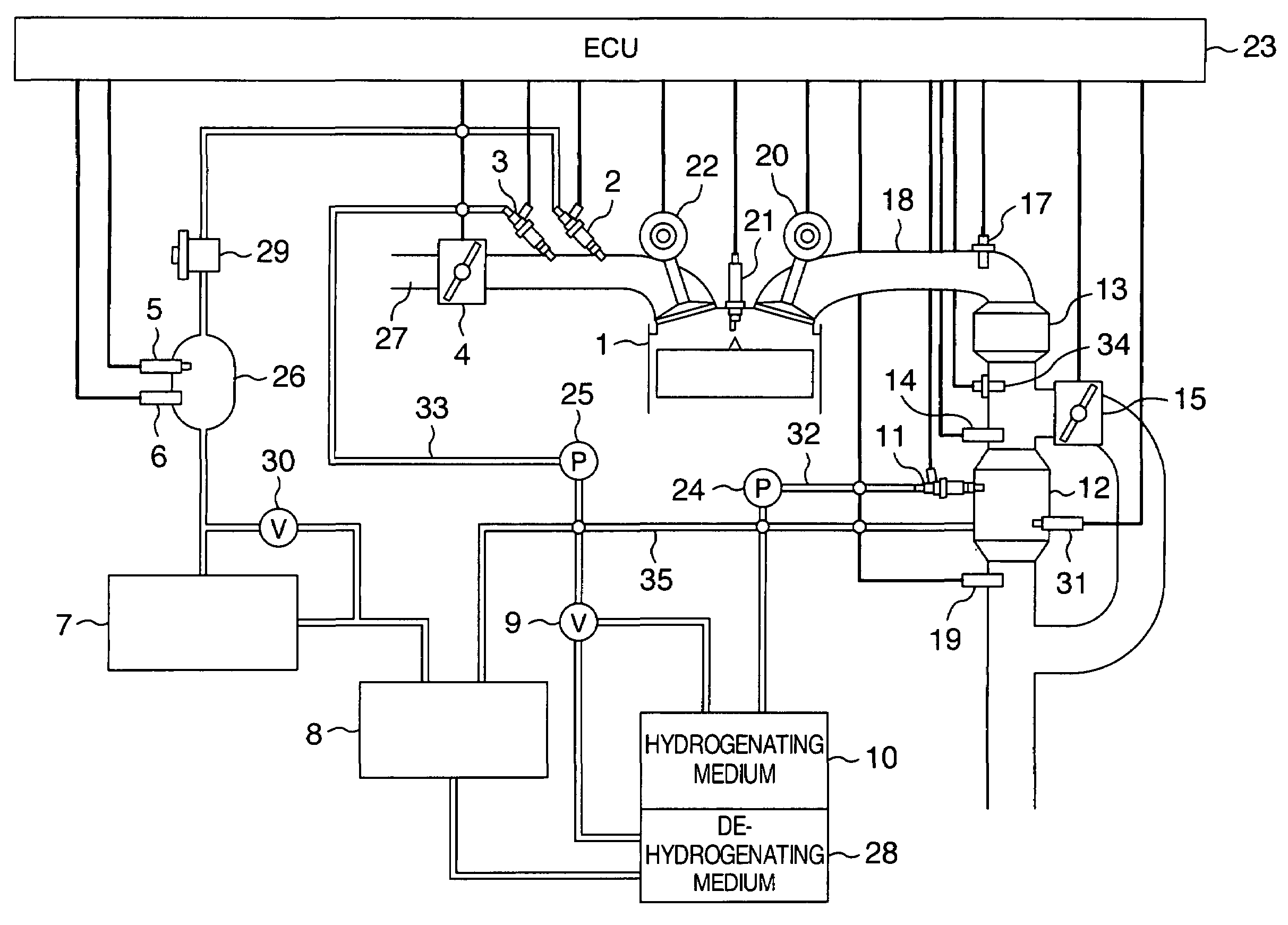
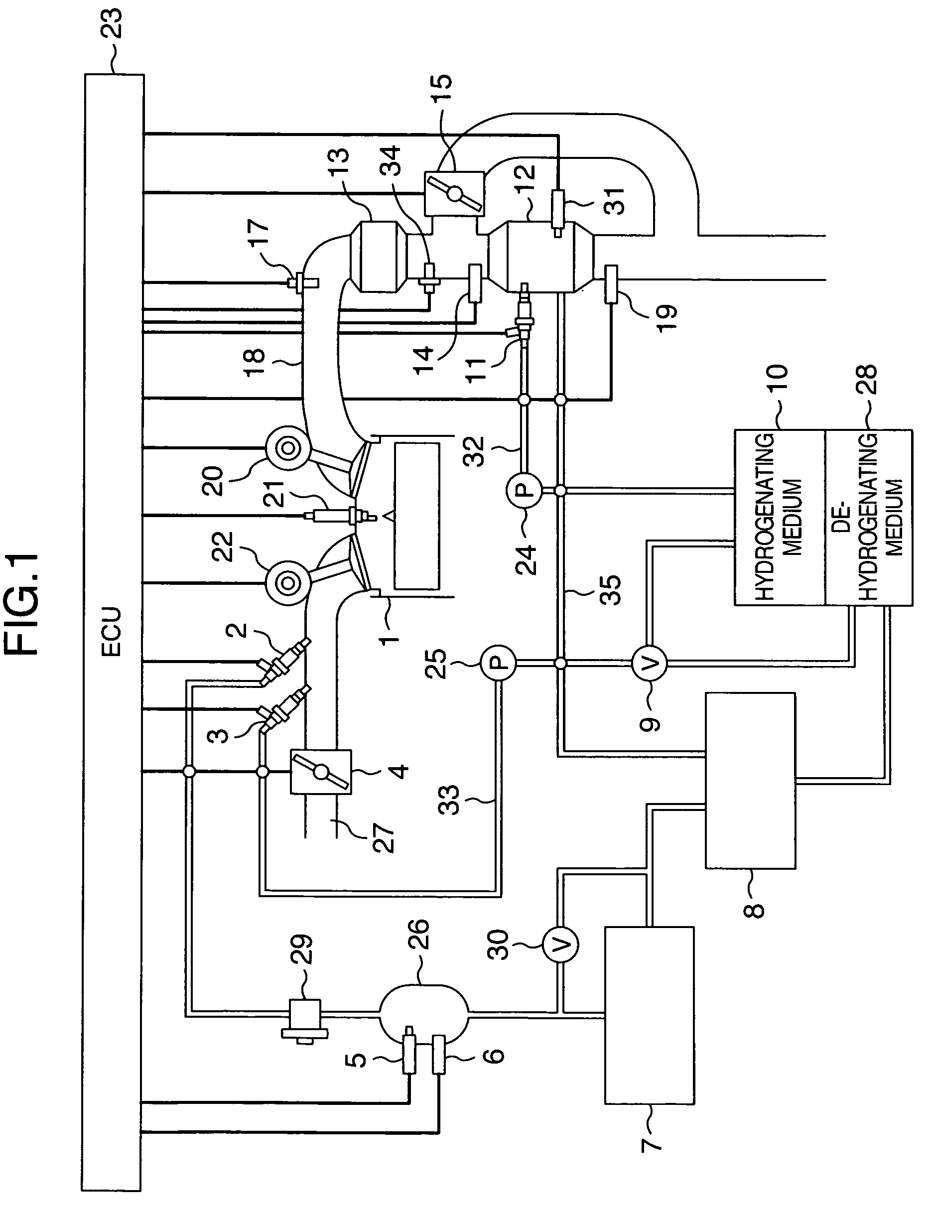
[0043]FIG. 1 shows a system which can utilize a heat of an exhaust gas discharged from an engine 1 by installing a hydrogen supplying apparatus 12 for executing a dehydrogenation reaction of a medium chemically repeating a hydrogen absorption and a hydrogen desorption in an exhaust pipe 18 of the engine. An amount of the exhaust gas supplied to the hydrogen supplying apparatus 12 can be adjusted by using an exhaust gas amount adjusting valve 15. Further, temperature detecting means 14, 19 and 31 are respectively installed in an upstream side and a downstream side of the hydrogen supplying apparatus 12, and within the hydrogen supplying apparatus 12. A hydrogenating medium is supplied to the hydrogen supplying apparatus 12 by a hydrogenating medium supplying apparatus 11.

[0044]The medium mentioned above includes a hydrocarbon fuel such as a gas...


PUM


Abstract

An object of the invention is to provide an engine system driving an engine by using a hydrogen rich gas generated from a medium chemically repeating a hydrogen absorption and a hydrogen desorption as one of fuels, in which the engine system can efficiently generate a hydrogen rich gas from the medium. In an engine system which mounts a medium chemically repeating a hydrogen absorption and a hydrogen desorption thereon, is provided with a hydrogen supplying apparatus generating or storing a hydrogen rich gas from the medium, and drives an engine by using the hydrogen rich gas as one of fuels, the engine system has a detecting portion detecting an operating state of the engine, and a medium supplying amount control means controlling a supplying amount of the medium supplied to the hydrogen supplying apparatus in correspondence to a result of detection of the detecting portion.

Description

BACKGROUND OF THE INVENTION[0001](1) Field of the Invention[0002]The present invention relates to a hydrogen engine system in which a medium chemically repeating a hydrogen absorption and a hydrogen desorption is mounted.[0003](2) Description of Related Art[0004]As a conventional system driving an engine by using a hydrogen rich gas generated from a medium chemically repeating a hydrogen absorption and a hydrogen desorption as one of fuels, there is disclosed a hydrogen utilizing internal combustion engine which can supply the medium mentioned above to an engine in addition to the hydrogen rich gas generated from the medium mentioned above, and can independently supply both of them to the engine, for example, as described in patent document 1.[0005]Patent Document 1: JP-A-2005-147124[0006]In an engine system using a hydrogen rich gas generated from a medium chemically repeating a hydrogen absorption and a hydrogen desorption as one of fuels, and driving an engine only by the hydroge...

Claims


Application Information

Patent Timeline
Patent Type & Authority Patents(United States)
IPC IPC(8): F02B43/08F02B13/00F02B17/00
CPCC01B3/0015F02D19/0628F02M21/0206F02M25/12F02D19/0692F02D19/0634F02D19/0644F02D19/0671Y02E60/328Y02T10/121Y02T10/32F02D19/0615F02D19/0689Y02T10/36Y02E60/32Y02T10/12Y02T10/30
Inventor SHIMADA, ATSUSHIISHIKAWA, TAKAOITABASHI, TAKEYUKIKANEMOTO, HIROSHI
Owner HITACHI LTD
Why Eureka
Try Eureka