
Compact disk device and disk drive

a disk drive and compact technology, applied in the direction of windings, record information storage, instruments, etc., can solve the problems of reducing the performance of the disk drive, reducing the saturation of the magnetic flux density that passes through the stator core, and reducing the width. , to achieve the effect of small thickness, small size and high efficiency

Inactive Publication Date: 2009-08-04
WESTERN DIGITAL TECH INC
View PDF10 Cites 2 Cited by
  • Summary
  • Abstract
  • Description
  • Claims
  • Application Information

AI Technical Summary

Benefits of technology

[0004]According to the above patent documents 1 to 3, the magnetic disk device can be formed having a decreased thickness. However, spaces are great among the neighboring coils causing a decrease in the performance of the disk drive and a decrease in the width of the stator core correspondingly, resulting in a decrease in the saturation of the magnetic flux density that passes through the stator core. That is, performance of the disk drive is basically greatly affected by the volume of the magnetic circuit in the stator, while spaces among the neighboring coils do not function as magnetic circuits. It is therefore important to reduce wasteful spaces among the coils as much as possible from the standpoint of enhancing performance of the disk drive.
[0005]It is a feature of the present invention to realize a disk device and a disk drive featuring a small size, a small thickness, a high efficiency, a small degree of vibration and a small level of noise by increasing the volume of the stator core by reducing as much as possible the wasteful spaces that do no work as magnetic circuits.
[0012]The present invention realizes a disk device and a disk drive featuring a small size, a small thickness, a high efficiency, a small degree of vibration and a small level of noise by increasing the volume of the stator core by reducing as much as possible the wasteful spaces that do no work as magnetic circuits.

Problems solved by technology

However, spaces are great among the neighboring coils causing a decrease in the performance of the disk drive and a decrease in the width of the stator core correspondingly, resulting in a decrease in the saturation of the magnetic flux density that passes through the stator core.
That is, performance of the disk drive is basically greatly affected by the volume of the magnetic circuit in the stator, while spaces among the neighboring coils do not function as magnetic circuits.

Method used


Image

  • Compact disk device and disk drive
  • Compact disk device and disk drive
  • Compact disk device and disk drive

Examples


Embodiment Construction

[0022]A disk drive according to an embodiment of the invention will now be described.

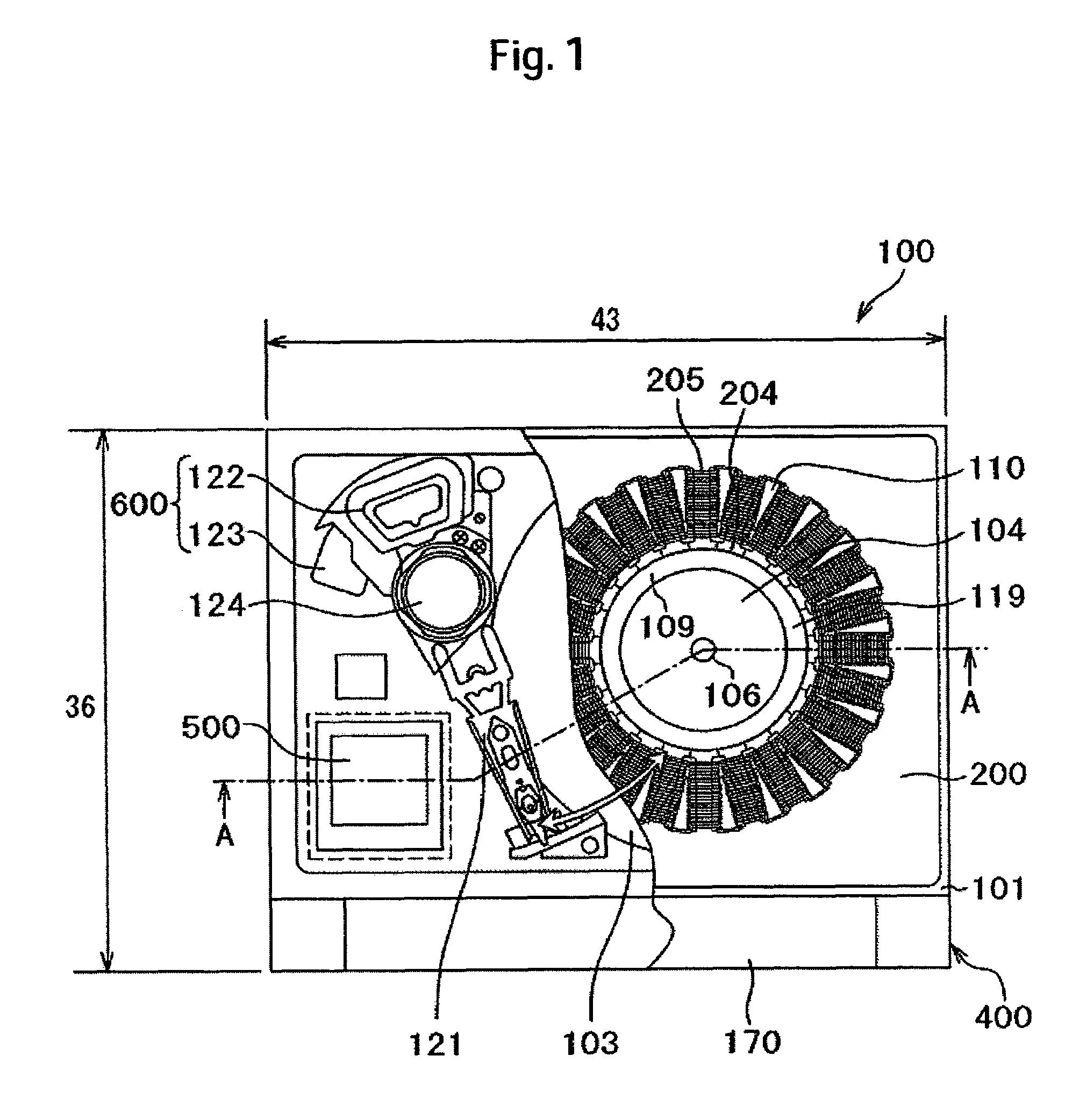
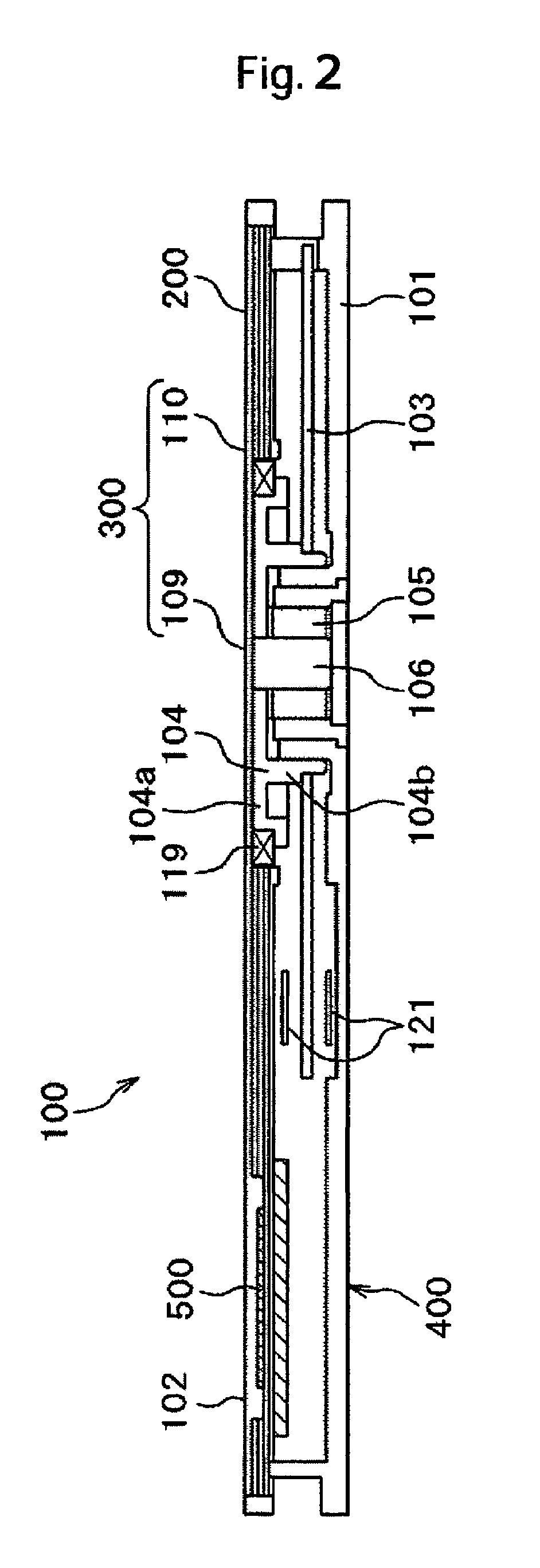
[0023]Described below, first, with reference to FIGS. 1 and 2 is a whole magnetic disk device 100. FIG. 1 is a top view of a magnetic disk device 100 according to an embodiment of the invention, and FIG. 2 is a sectional view along A-A in FIG. 1. Here, FIG. 1 illustrates a state where a cover 102 is omitted and a metal core substrate 200 is partly cut away.

[0024]The magnetic disk device 100 includes a magnetic disk 103, a disk drive unit 300 for driving the magnetic disk 103, a magnetic head, a suspension 121 for supporting the magnetic head, a head drive unit 600 for moving the magnetic head via the suspension 121 to bring it to a predetermined position, a control unit 500 for controlling the drive units 300, 600, and a housing 400 for incorporating them, as principal constituent elements. The magnetic disk device 100 of this embodiment has an outer size (43 mm×36 mm×3.3 mm) which is the same as th...


PUM


Abstract

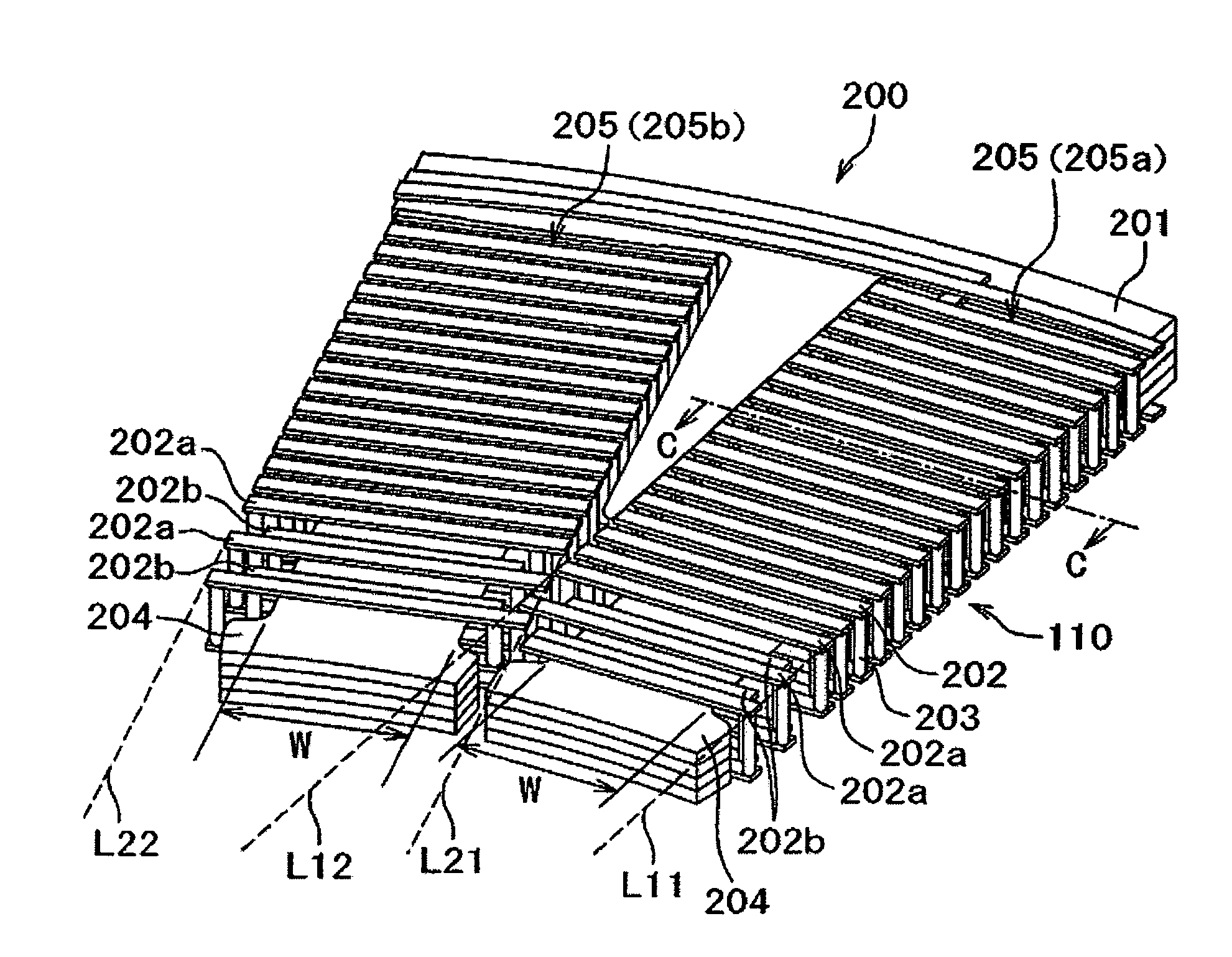
A disk device has a small size, a small thickness, a high efficiency, a small degree of vibration and a small level of noise. In one embodiment, the disk device comprises a disk for storing information and a disk drive for driving the disk. The disk drive includes a rotor portion mounting an annular permanent magnet on the outer peripheral portion thereof, and a stator portion disposed on the outer side in the radial direction of the annular permanent magnet. The stator portion is constituted by a wiring board provided with a stator core formed by laminating magnetic metal plates in a radial manner and a coil that is so formed as to surround the stator core while electrically connecting wiring layers and through hole portions. The coil is so formed that among the envelopes connecting the outermost peripheral surfaces of the coil in the radial direction, the neighboring envelops and intersect at an inner position in the radial direction.

Description

CROSS-REFERENCES TO RELATED APPLICATIONS[0001]This application claims priority from Japanese Patent Application No. JP2005-184615, filed Jun. 24, 2005, the entire disclosure of which is incorporated herein by reference.BACKGROUND OF THE INVENTION[0002]This invention relates to a disk device and to a disk drive, such as a magnetic disk device, a flexible disk drive, a magnetic-optic disk drive, an optical disk drive, an optical hologram disk drive and a disk drive used therefore.[0003]Conventional magnetic disk devices have been disclosed in JP-A-2003-79119 (patent document 1), JP-A-2004-32829 (patent document 2) and JP-A-2004-32926 (patent document 3). These magnetic disk devices include a magnetic disk for storing information and a disk drive for driving the magnetic disk. The disk drive includes rotor portions mounting an annular permanent magnet on the outer peripheral portion thereof, and stator portions disposed on the outer side in the radial direction of the annular permanent...

Claims


Application Information

Patent Timeline
Patent Type & Authority Patents(United States)
IPC IPC(8): H02K3/00H02K3/26
CPCG11B19/2009H02K1/148H02K11/0073H02K3/522H02K3/26H02K11/33
Inventor FUJITA, YUJIAMANO, YASUOYAMAGUCHI, YOSHIHIDE
Owner WESTERN DIGITAL TECH INC
Learn More