Data transfer apparatus for low voltage differential signaling

a data transfer and differential signaling technology, applied in the direction of dc level restoring means or bias distortion correction, receiver monitoring, pulse technique, etc., can solve the problems of undetectable increase in signal loss, etc., to improve simplify the circuit configuration, and improve the effect of the feedback control of the amplitude of the lvds signal

Inactive Publication Date: 2009-08-04
RENESAS ELECTRONICS CORP
View PDF6 Cites 11 Cited by
  • Summary
  • Abstract
  • Description
  • Claims
  • Application Information

AI Technical Summary

Benefits of technology

[0018]In detail, an object of the present invention is to provide a data transmission apparatus which detects an amplitude of a LVDS signal without affecting impedance matching of transmission lines, and thereby achieves improved feedback control of the amplitude of the LVDS signal.
[0019]Another object of the present invention is to provide a data transmission apparatus which detects an amplitude of a LVDS signal with simplified circuit configuration, and thereby achieves improved feedback control of the amplitude of the LVDS signal.

Problems solved by technology

One drawback of the conventional technique is that the architecture using the coupler 141 and the demodulator 142 undesirably experiences increased signal loss.
Disposing the coupler 141 inevitably affects the impedance matching of the transmission line 104 connected to the coupler 141, and thus causes an increase in the signal loss.
The increased signal loss undesirably deteriorates the detection accuracy of the amplitudes.
This problem is especially serious if the transmission lines 104 experiences increased loss.
Another drawback is that the aforementioned architecture enhances complexity and size of the circuitry used for the detection of the amplitudes, because the architecture requires a high-speed amplifier adapted to high frequency ranges of the LVDS signals.
This undesirably enhances complexity and size of the required amplifier.
Still another drawback of the architecture shown in FIG. 1 is that the architecture does not deal with common mode noise, because the coupler 141 is coupled to only one of the pair of the signal lines.
These drawbacks prevent desirable feedback control of the amplitude of the differential signal.

Method used


Image

  • Data transfer apparatus for low voltage differential signaling
  • Data transfer apparatus for low voltage differential signaling
  • Data transfer apparatus for low voltage differential signaling

Examples


first embodiment

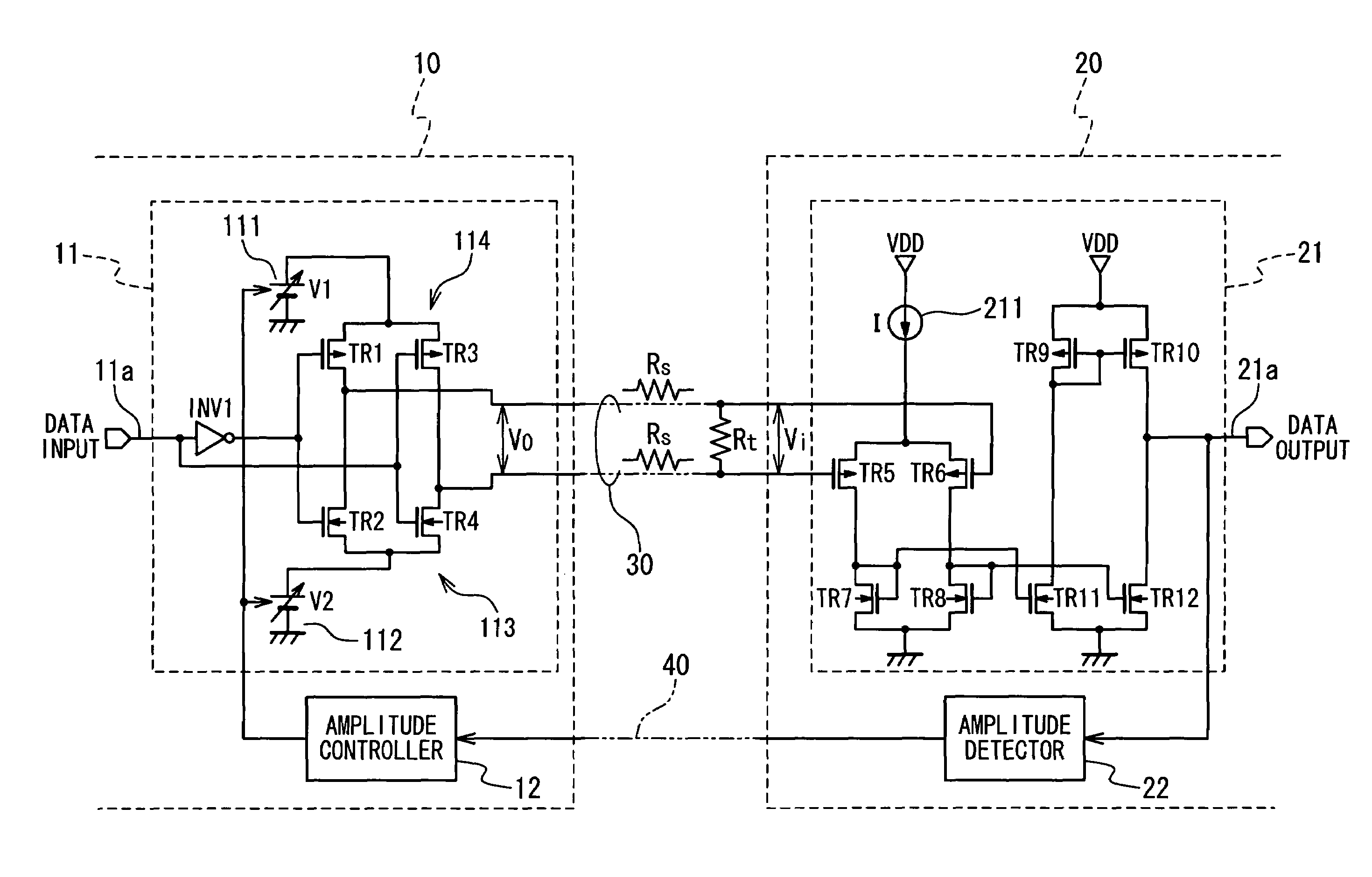
[0039]In a first embodiment, as shown in FIG. 3, a data transmission apparatus is composed of a transmitter 10, and a receiver 20. The transmitter 10, and the receiver 20 are connected through a transmission line 30 including a pair of twisted signal lines. A feedback signal line 40 is additionally interposed between the transmitter 10, and the receiver 20.

[0040]The transmitter 10 includes an output buffer 11 and an amplitude controller 12. The output buffer 11 generates a differential signal in response to a transmission data signal 11a inputted thereto. The amplitude controller 12 controls the amplitude of the differential signal generated by the output buffer 11 in response to a feedback signal received from the receiver 20 through the feedback signal line 40.

[0041]The receiver 20 includes an input buffer 21 and an amplitude detector 22. The input buffer 21 receives the differential signal from the transmitter 10 through the transmission line 30, and converts the received differe...

second embodiment

[0069]FIG. 7 is a circuit diagram illustrating a structure of a data transmission apparatus in a second embodiment. The data transmission apparatus in the data transmission apparatus is comprised of a transmitter 10′ which includes an open-drain type output buffer 51 in place of the output buffer 11 shown in FIG. 3. Additionally the transmitter 10′ includes an amplitude controller 12′ providing a set of amplitude control signals C0 through C2 for the output buffer 51. The output buffer 51 includes first and second drivers 512 and 513, and first and second selectors 513 and 514 connected to the first and second drivers 512 and 513, respectively.

[0070]Each of the drivers 512 and 513 is composed of a plurality of n transistors having different drive capabilities; n is an integer equal to or more than 2. It should be noted that the term “drive capability” of a specific transistor means that the maximum current through the transistor when the transistor is turned on. The drive capabiliti...


PUM


Abstract

A data transfer apparatus is composed of a transmitter and a receiver. The transmitter includes an output buffer developing a differential signal in response to a data signal, and an amplitude controller. The receiver includes an input buffer converting the differential signal into a single-end signal, and an amplitude detector developing a feedback signal in response to the single-end signal. The amplitude controller controls an amplitude of the differential signal in response to the feedback signal.

Description

BACKGROUND OF THE INVENTION[0001]1. Field of the Invention[0002]The present invention is generally related to data transfer apparatuses, more particularly, to data transfer apparatuses for low voltage differential signaling.[0003]2. Description of the Related Art[0004]Low voltage differential signaling (LVDS) is a well-known technique for achieving high-speed data transmission with reduced electromagnetic interference (EMI). In order to suppress EMI, LVDS-based data transmission apparatuses use differential signals having reduced amplitudes as far as data are successfully transferred.[0005]Pre-emphasis is known in the art as one of the techniques for improving reliability of LVDS data transmission. Japanese open Laid Patent Application No. P2002-368600A discloses a pre-emphasis circuit for boosting the amplitudes of edge portions of differential signals.[0006]Adjusting amplitudes of differential signals is another technique for improving data transmission reliability. Data transmiss...

Claims


Application Information

Patent Timeline
Patent Type & Authority Patents(United States)
IPC IPC(8): H04L25/06G06F3/00H03K5/08H03K5/22H04B3/18H04B3/50H04L25/02H04L25/45
CPCH03K5/086H04B17/24H04L25/45
Inventor HORI, YOSHIHIKONAKAJIMA, KEIICHI
Owner RENESAS ELECTRONICS CORP
Why Eureka
Try Eureka