Droplet ejection head driving circuit and method, and droplet ejection device

a technology of droplet ejection and driving circuit, which is applied in the direction of printing, etc., can solve the problems of difficult to reduce power consumption and ink solidification in the recording head and at the nozzle face, and achieve the effect of preventing ink solidification and reducing power consumption

Inactive Publication Date: 2009-08-11
FUJIFILM BUSINESS INNOVATION CORP
View PDF1 Cites 46 Cited by
  • Summary
  • Abstract
  • Description
  • Claims
  • Application Information

AI Technical Summary

Benefits of technology

[0010]The present invention will provide a droplet ejection head driving circuit and method which are capable of reducing power consumption in a non-printing mode, while preventing solidification of ink and the like, and a droplet ejection device.

Problems solved by technology

Consequently, solidification of ink in ink channels within the recording head and at a nozzle face has become a problem.
However, in the standby state, because prompt printing is required when printing data has been inputted, it is difficult to lower the power consumption.

Method used


Image

  • Droplet ejection head driving circuit and method, and droplet ejection device
  • Droplet ejection head driving circuit and method, and droplet ejection device
  • Droplet ejection head driving circuit and method, and droplet ejection device

Examples


first exemplary embodiment

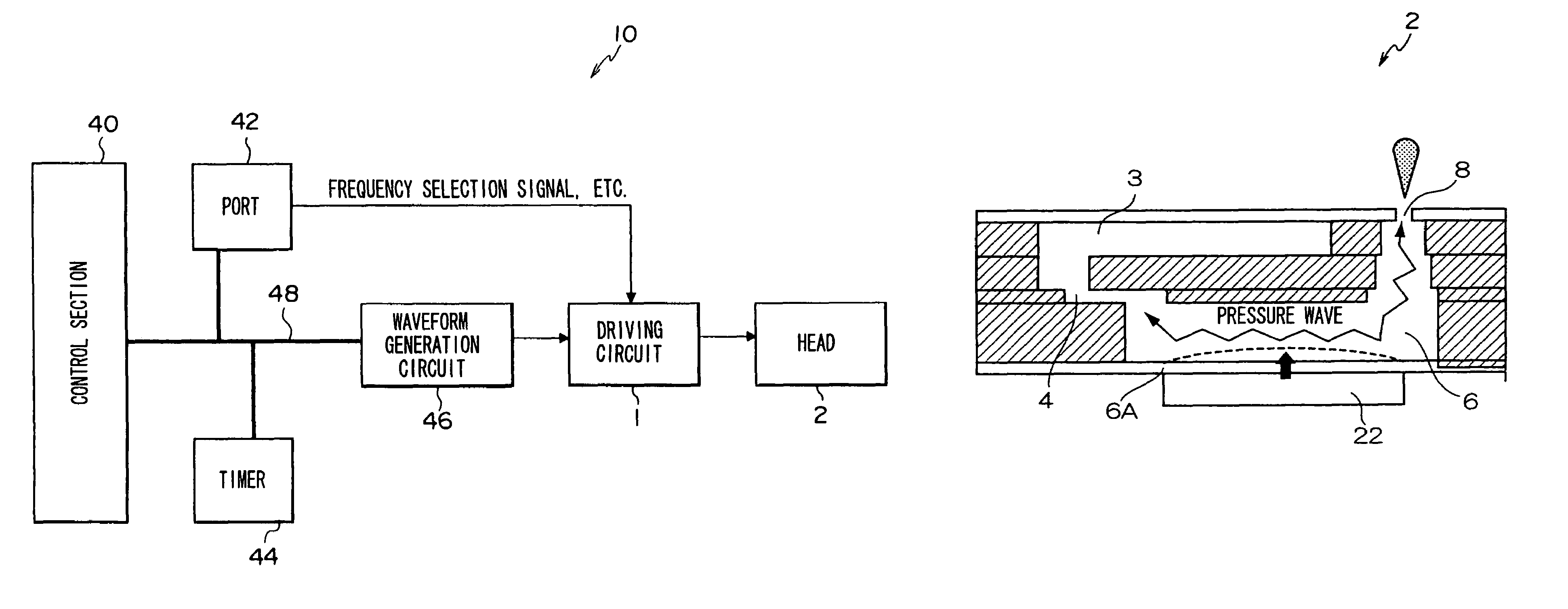
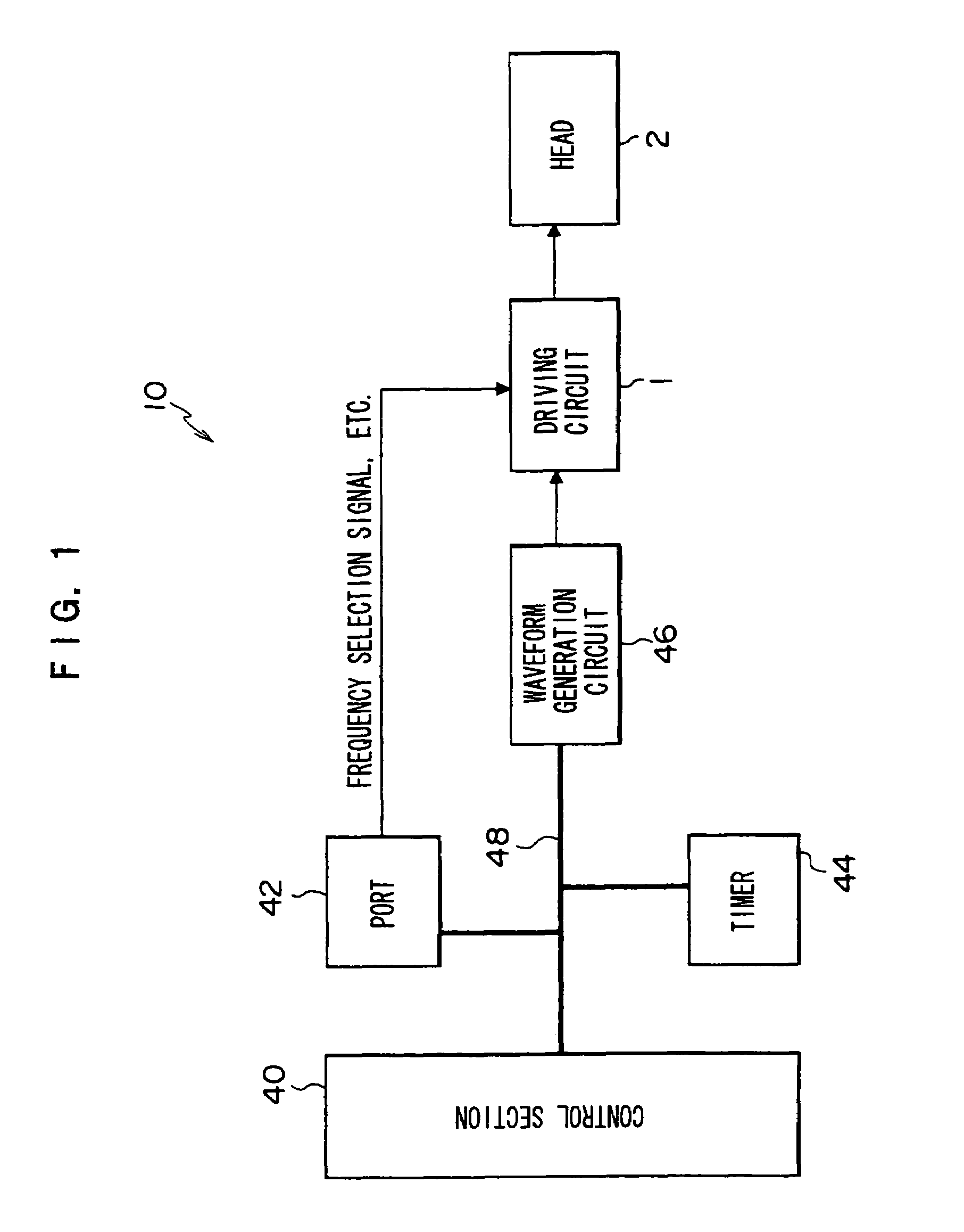
[0028]FIG. 1 shows a schematic block diagram of a control system of a droplet ejection device 10. As shown in FIG. 1, the droplet ejection device 10 is structured with a driving circuit 1, a head 2, a control section 40, a port 42, a timer 44 and a waveform generation circuit 46. The control section 40, port 42, timer 44 and waveform generation circuit 46 are connected via a bus 48.

[0029]The droplet ejection device 10 operates in respective modes of a preliminary state (warm-up), an operation state (running), a waiting state (stand-by), and a paused state (sleep). The warm-up state is a state in which, for example, initialization processing and the like for an unillustrated memory, logic circuit and the like of the droplet ejection device 10 is executed. The running state is a state during execution of printing in accordance with inputted printing data. The standby state is a state from which is possible to commence printing promptly when printing data is received. The sleep state i...

second exemplary embodiment

[0127]Next, a second exemplary embodiment of the present invention will be described. Herein, portions that are the same as in the first embodiment are assigned the same reference numerals, and detailed descriptions thereof will not be given.

[0128]For the second exemplary embodiment, a droplet ejection device will be described which is capable of preventing a change in amplitude of the triangular wave when the printing mode is switched to the non-printing mode and the switching frequency is lowered.

[0129]Firstly, in FIG. 6, if the upper side input voltage of the differential amplifier 30 (i.e., the voltage at position A in FIG. 6) is V1, the lower side input voltage (the voltage at position B in FIG. 6) is V2, the output voltage of the differential amplifier 30 (the voltage at position C in FIG. 6) is V3, and the resistance values of resistors R31 to R34 are R31, R32, R33 and R34, respectively, the following equation applies.

V3=k{VB+(V2−V1)}  (2)

Therein,

k=R33 / R31=R34 / R32=VB / Vcc  (3)...


PUM


Abstract

A driving circuit of a droplet ejection head which, by supplying analog driving signals to driving elements, ejects droplets from nozzles which are provided in correspondence with the driving elements. The driving circuit includes a driving signal generation unit, a pulse modulation unit, a switching signal generation unit, an amplification unit and a frequency-setting unit. The driving signal generation unit selectively outputs a first and a second analog driving signal. The pulse modulation unit pulse-modulates the analog driving signal and outputs a digital signal. The switching signal generation unit generates a switching signal. The amplification unit amplifies the digital signal by switching in accordance with the switching signal, and supplies the amplified digital signal to the driving elements. The frequency-setting unit sets a switching frequency of the switching signal in accordance with a frequency selection signal, which corresponds to the analog driving signal.

Description

BACKGROUND[0001]1. Technical Field[0002]The present invention relates to a droplet ejection head driving circuit and method and a droplet ejection device, and more specifically relates to a droplet ejection head driving circuit and method for supplying driving signals to a droplet ejection head in order to agitate ink, even in a non-printing mode, and to a droplet ejection device therewith.[0003]2. Related Art[0004]High-speed recording is possible with an inkjet recording apparatus which employs a long head in which short head units (short heads) are joined together (for example, a full width array (FWA) head, which is to say, a head which is lengthened to the width of paper). Accordingly, in recent years, the development of inkjet recording apparatuses which employ these long heads has proceeded apace.[0005]In an inkjet recording apparatus which employs this long head, a water content of ink may be reduced in order to prevent swelling of paper, and a processing fluid may be employe...

Claims


Application Information

Patent Timeline
Patent Type & Authority Patents(United States)
IPC IPC(8): B41J2/05
CPCB41J2/0452B41J2/04541B41J2/04551B41J2/04596B41J2/04581B41J2/04588B41J2/04568
Inventor ISHIZAKI, SUNAO
Owner FUJIFILM BUSINESS INNOVATION CORP
Why Eureka
Try Eureka