
Anticoagulant and thrombo-resistant hollow fiber membranes for in-vivo plasmapheresis and ultrafiltration

a hollow fiber membrane and plasmapheresis technology, applied in the direction of membranes, filtration separation, separation processes, etc., can solve the problems of inconvenient for some patients, risk of bleeding, and general degradation of membrane performance, so as to reduce thrombosis formation and pore fouling

Inactive Publication Date: 2009-08-11
TRANSVIVO
View PDF30 Cites 13 Cited by
  • Summary
  • Abstract
  • Description
  • Claims
  • Application Information

AI Technical Summary

Benefits of technology

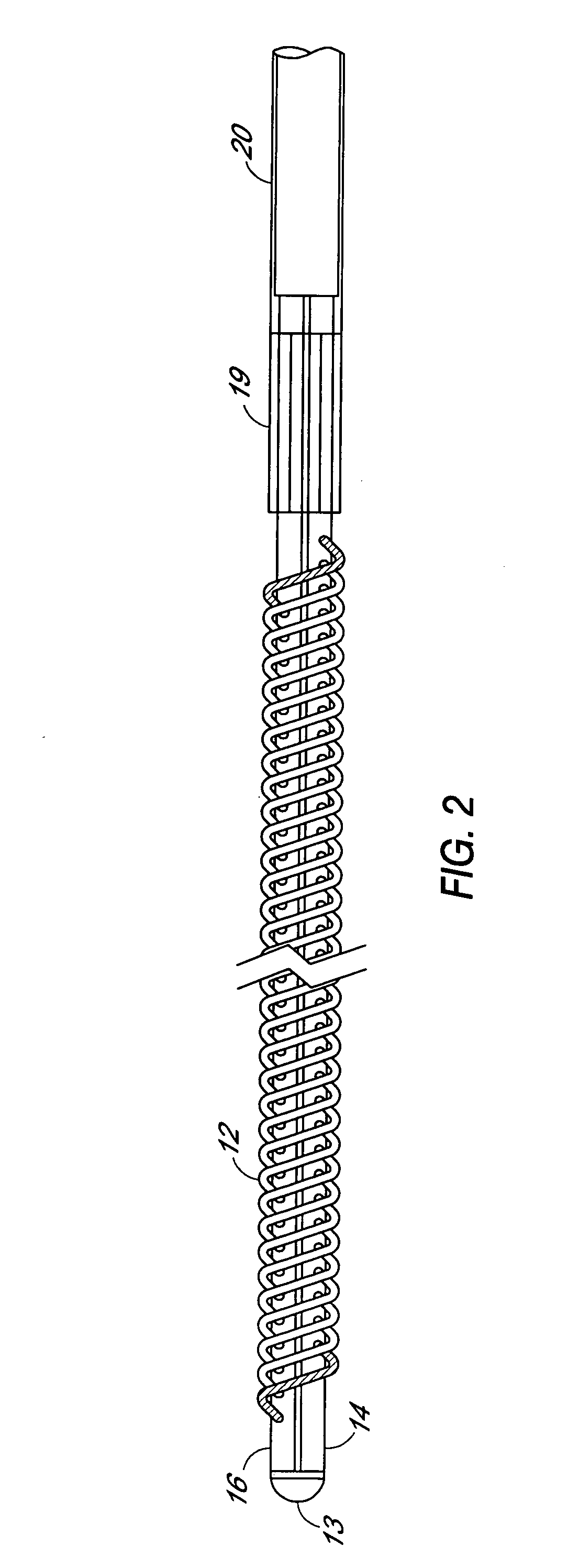
[0004]The invention described herein comprises asymmetrical microporous hollow fiber membranes which may be implanted in a patient's blood vessel for carrying out in-vivo plasmapheresis and / or in-vivo ultrafiltration as previously described and which membranes are further characterized by a nitric oxide donor composition distributed on or in the fiber wall capable of releasing nitric oxide or inducing nitric oxide production or release in-vivo. The nitric oxide donor composition may be coated, embedded, impregnated, bonded, absorbed, immobilized or otherwise incorporated on or in the membrane fiber wall. Release of nitric oxide within the fiber wall or at the fiber wall surface exposed to blood in-vivo reduces thrombosis formation and pore fouling during plasmapheresis and / or ultrafiltration. In a preferred embodiment, the aforesaid fibers are used in a filter device comprising one or more elongated hollow tubes on which the fibers are secured.

Problems solved by technology

During use, the relatively small pores at or adjacent to the outer fiber surface become clogged or occluded with particulate matter from the permeate (blood) whereby performance of the membranes is generally degraded over time.
However, because the use of heparin in the backflush may increase the risk of bleeding, it may not be suitable for some patients.

Method used


Image

  • Anticoagulant and thrombo-resistant hollow fiber membranes for in-vivo plasmapheresis and ultrafiltration
  • Anticoagulant and thrombo-resistant hollow fiber membranes for in-vivo plasmapheresis and ultrafiltration

Examples


Embodiment Construction

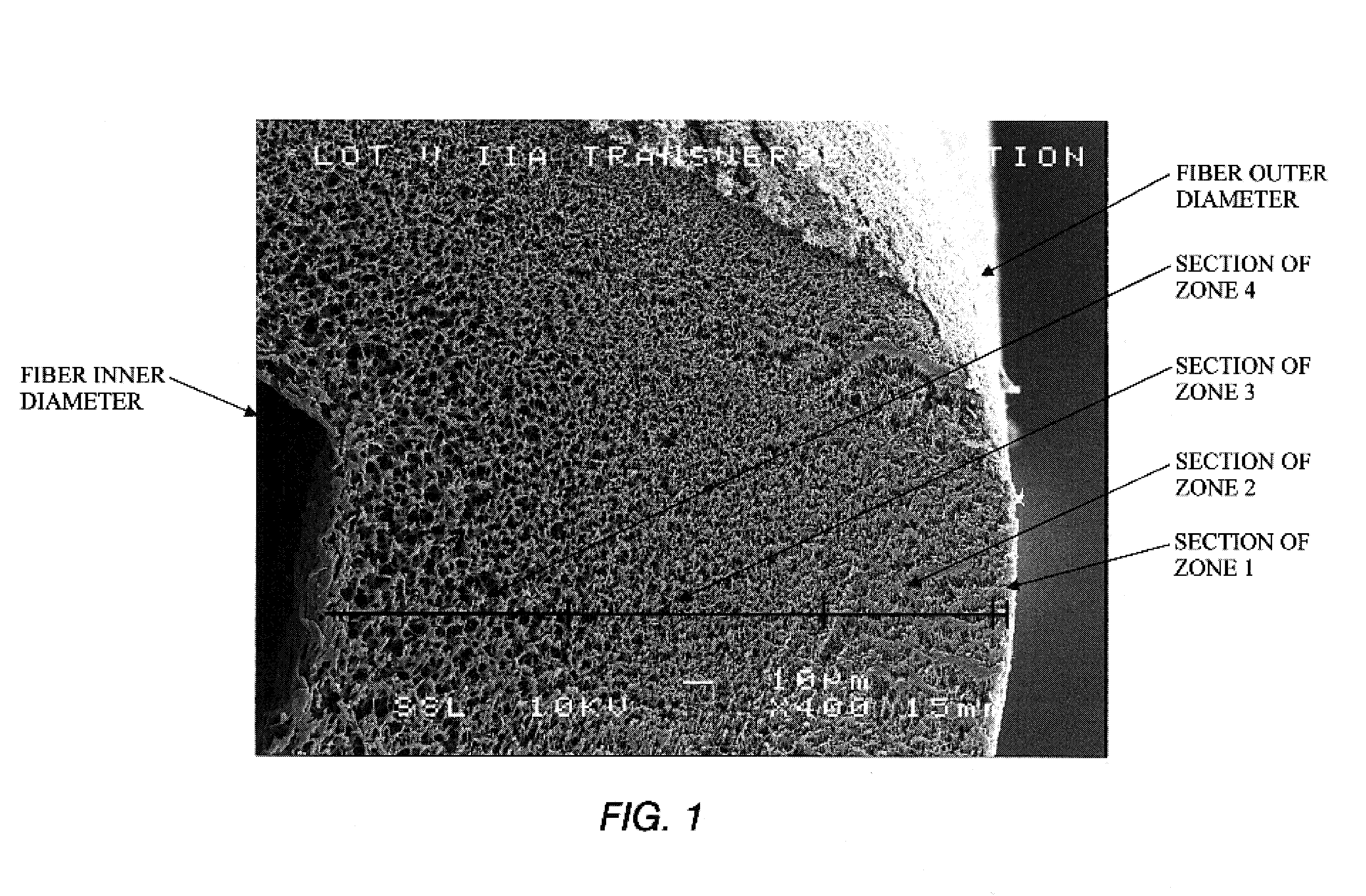
[0007]As illustrated in FIG. 1, the features of the fiber wall of the membrane of the invention include a pore and void structure defined within frames or solid walls which form boundaries of the pores. The pores are voids of variable definitive sizes which permit passage of fluid through the fiber wall to the lumen and which pores obstruct the passage of components larger than the pore diameter. The pores are irregular-shaped voids bounded by solid frames to form irregular tortuous paths for irregular and regular-shaped solutes. The wall structure of the fiber from the outer surface to the lumen is a continuum with non-linear pore and void distribution. The resulting structure is a continuous change in mass density between the outer surface of the fiber and the inner lumen surface and whereby the pore size gradually changes between the fiber wall surfaces. The fiber wall illustrated is substantially without macrovoids. The fiber wall structure of the elongated microporous fibers is...


PUM

PropertyMeasurementUnit
pore diameteraaaaaaaaaa

Abstract

An in-vivo plasmapheresis or in-vivo ultrafiltration membrane comprises a plurality of elongated hollow microporous fibers each fiber having an outer wall, an inner wall and an interior lumen extending along the length thereof and defined by an inner wall surface, and wherein the fiber wall structure is a substantially continuous change in mass density from the outer wall to the inner wall and comprises a continuum of voids bounded by solid frames, the fiber wall having an asymmetrical pore size and asymmetrical mass density between said inner wall surface and the outer wall surface with a higher mass density adjacent to the outer wall and a lower mass density adjacent to said inner wall, and characterized by a nitric oxide donor composition capable of producing or releasing nitric oxide or inducing nitric oxide production or release in-vivo with a blood vessel, distributed on or in the fiber wall.

Description

CROSS-REFERENCE TO RELATED APPLICATIONS[0001]This application is a continuation-in-part of application Ser. No. 10 / 959,918 filed Oct. 6, 2004, now U.S. Pat. No. 7,195,711, which is a continuation-in-part of application Ser. No. 10 / 666,185 filed Sep. 17, 2003, now U.S. Pat. No. 6,802,971, which is a divisional of application Ser. No. 09 / 549,131 filed Apr. 13, 2000, now U.S. Pat. No. 6,802,820.BACKGROUND OF THE INVENTION[0002]In U.S. Pat. Nos. 6,802,820 and 6,802,971 and application Ser. No. 10 / 959,918, now U.S. Pat. No. 7,195,711, there are described hollow fiber membranes capable of in-vivo plasmapheresis and / or in-vivo ultrafiltration. The aforesaid patents and application are incorporated herein by reference in their entirety, respectively. The described membranes comprise elongated hollow microporous fibers having an asymmetrical pore size and asymmetrical mass density between the inner and outer wall surfaces with a higher mass density adjacent to the outer wall and a lower mass...

Claims


Application Information

Patent Timeline
Patent Type & Authority Patents(United States)
IPC IPC(8): B01D63/02B01D69/08B01D71/68
CPCA61M1/1678B01D67/0016B01D67/0088B01D67/0093B01D69/04B01D69/08B01D69/12B01D69/141B01D71/68B01D69/02A61M1/34B01D2325/022A61M1/3403A61M2205/3331
Inventor GORSUCH, REYNOLDS G.HANDLEY, JR., HAROLD H.PETERS, HAROLD W.KEARNS, JACOB C.
Owner TRANSVIVO
Learn More