Method and apparatus for controlling the reproduction in audio signals in electroacoustic converters

a technology of electroacoustic converter and audio signal, which is applied in the direction of tone control, transducer casing/cabinet/support, electrical transducer, etc., can solve the problems of unsatisfactory base reproduction and achieve the effect of avoiding distortion of audio signal, reducing requirements, and improving the quality of modified audio signals

Inactive Publication Date: 2009-08-11
GIGASET COMMUNICATIONS
View PDF11 Cites 14 Cited by
  • Summary
  • Abstract
  • Description
  • Claims
  • Application Information

AI Technical Summary

Benefits of technology

[0011]The advantage of the inventive method lies in the fact that the amplification of the harmonic original waves present in the audio signal guarantees a significantly better quality of the modified audio signals produced in the Digital Signal Processor. This particularly avoids distortions of the audio signal. In addition, the method in accordance with the present invention imposes lower requirements with regard to the computing power and the memory requirement in the Digital Signal Processor.
[0012]Thus, it is of advantage in accordance with another embodiment of the present invention if, when a “Finite Impulse Response” filter is—used, as opposed to an “Infinite Impulse Response” filter in accordance with—a further embodiment, for the audio signal to be combined with the amplified frequency components to be buffered in order to compensate for the combination of phase shifts based on the use of the FIR filter between the amplified frequency components and the audio signal.
[0013]In accordance with a further embodiment, it is advantageous if, to improve the quality of the modified audio signal output by the electroacoustic converters, the modified audio signal is filtered for amplification of selected frequencies.

Problems solved by technology

Electronic audio devices, in which such small electroacoustic converters are used and in which the base reproduction is consequently unsatisfactory, are primarily audio devices (devices for output or reproduction of audio signals) of communication and information technology as well as entertainment and consumer electronics, such as mobile radio and cordless handsets, notebooks, Personal Digital Assistants, mini radios, radio alarm clocks, portable music players, etc.

Method used


Image

  • Method and apparatus for controlling the reproduction in audio signals in electroacoustic converters
  • Method and apparatus for controlling the reproduction in audio signals in electroacoustic converters
  • Method and apparatus for controlling the reproduction in audio signals in electroacoustic converters

Examples


first embodiment

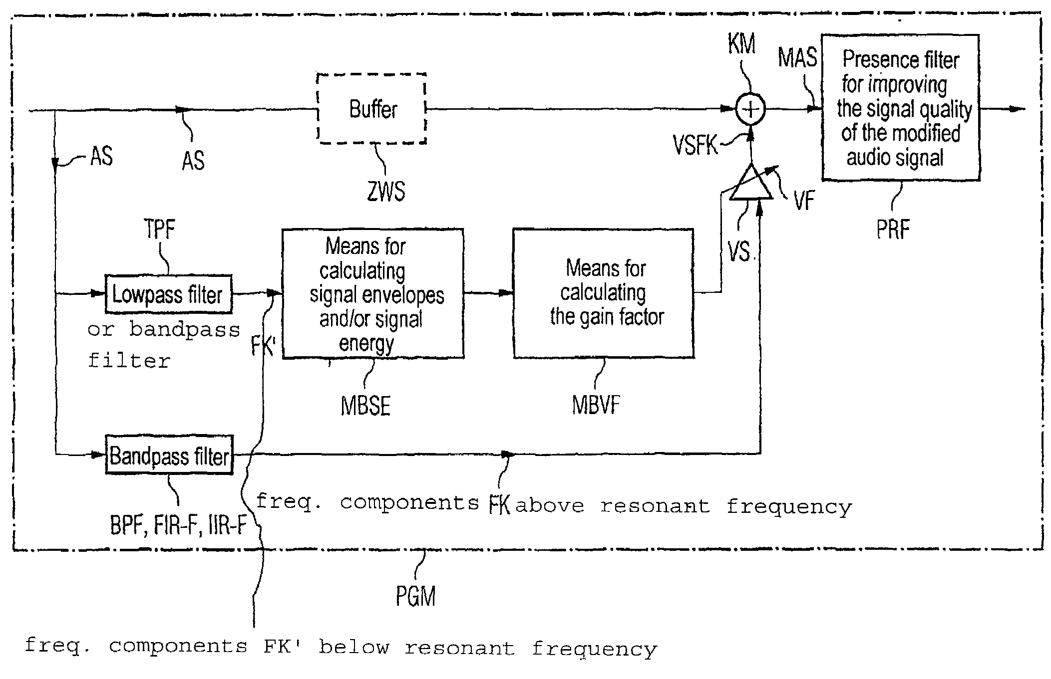
[0024]FIG. 4 shows the program module PGM in accordance with FIG. 2. The audio signal AS is bandpass filtered using a bandpass filter implemented by software BPS to isolate a first frequency component FK, and is filtered via a low pass filter TPF implemented by software to isolate a second frequency component FK′. While the first frequency component FK is being amplified, a gain factor VF determined by the amplification of the first frequency component FK is generated with the second frequency component FK′.

[0025]Instead of the low pass filter TPF, a further bandpass filter implemented via software can be used as an alternative, or even the bandpass filter which the first frequency component FK generates. In the latter case, the two frequency components FK, FK′ would be the same (FK=FK′).

[0026]The bandpass filter BPF is preferably embodied as a Finite Impulse Response filter (FIR filter) FIR-F or, alternatively, as an Infinite Impulse Response filter (IIR filter) IIR-F. If the bandp...

second embodiment

[0028]FIG. 5 uses FIG. 4 as a starting point to show program module PGM in accordance with FIG. 2. The audio signal AS is again bandpass filtered with the bandpass filter BPF for isolation of the first frequency component FK and lowpass filtered with the lowpass filter TPF for isolation of the second frequency component FK′. While the first frequency components FK is again being amplified, a gain factor VF determined by the amplification of the first frequency component FK is again generated with the second frequency component FK′.

[0029]Instead of the lowpass filter TPF, a further bandpass filter implemented via software again can be used as an alternative, or even the bandpass filter which the first frequency component FK generates. In the latter case, the two frequency components FK, FK′ would then again be the same (FK=FK′).

[0030]The bandpass filter BPF is again preferably embodied as a Finite Impulse Response filter (FIR filter) FIR-F or, alternatively, as an Infinite Impulse Re...

third embodiment

[0034]FIG. 6 uses FIG. 4 as a starting point to show program module PGM in accordance with FIG. 2. The audio signal AS is once more bandpass filtered with the bandpass filter BPF for isolation of the first frequency component FK and low pass filtered with the low pass filter TPF for isolation of the second frequency component FK′. While the first frequency component FK is being amplified, a gain factor VF determined by the amplification of the first frequency component FK is once again generated with the second frequency component FK′.

[0035]Instead of the lowpass filter TPF, a further bandpass filter implemented via software again can be used as an alternative, or even the bandpass filter which the first frequency component FK generates. In the latter case, the two frequency components FK, FK′ would be the same (FK=FK′).

[0036]The bandpass filter BPF is once more preferably embodied as a Finite Impulse Response filter (FIR filter) FIR-F or, alternatively, as an Infinite Impulse Respo...


PUM


Abstract

The aim of the invention is to control the bass reproduction of audio signals in electroacoustic transducers based on the psychoacoustic principle denoted by the term “virtual pitch” or “residual hearing (hearing of missing fundamental)”, in such a way that the perception of the virtual bass reproduction of the audio signals is improved in relation to prior art. To this end, the reproduction of the low pitched frequencies or basses released in the electroacoustic transducer is controlled by the amplification of the harmonic waves already contained in the audio signals, in the form of a simulation, in such a way that the listener experiences or perceives an improved bass reproduction. The control or simulation can thus be carried out in both a digital manner, by means of a program module in a digital signal processor of an electronic appliance for outputting and / or reproducing audio signals using the electroacoustic transducer, and in an analog manner, by means of a hardware circuit between a digital analog transducer and a final amplifier of the electronic appliance for outputting and / or reproducing audio signals using the electroacoustic transducer.

Description

BACKGROUND OF THE INVENTION[0001]The bass reproduction of audio signals in an electroacoustic converter, particularly a loudspeaker or an earpiece, is governed by the size of the electroacoustic converter (the loudspeaker of the earpiece). The smaller the loudspeaker membrane and its maximum deflection area, the higher the lower resonant frequency.[0002]FIG. 1 shows a typical frequency curve of a small loudspeaker. Electronic audio devices, in which such small electroacoustic converters are used and in which the base reproduction is consequently unsatisfactory, are primarily audio devices (devices for output or reproduction of audio signals) of communication and information technology as well as entertainment and consumer electronics, such as mobile radio and cordless handsets, notebooks, Personal Digital Assistants, mini radios, radio alarm clocks, portable music players, etc.[0003]To improve the bass reproduction with a small loudspeaker, a known psychoacoustic principle can be em...

Claims


Application Information

Patent Timeline
Patent Type & Authority Patents(United States)
IPC IPC(8): H03G5/00H04R3/04
CPCH04R3/04
Inventor AUBAUER, ROLANDKLINKE, STEFANO AMBROSIUS
Owner GIGASET COMMUNICATIONS
Why Eureka
Try Eureka