Electromagnetic shielding

a technology of electromagnetic shielding and shielding chamber, applied in the field of electromagnetic shielding, can solve the problems of not being able to achieve the effect of practical electromagnetic shielding, not being able to protect technical installations, and being able to disturb or destroy all electronic circuits. achieve good electric connection

Active Publication Date: 2009-08-18
KESSEL WOLFGANG
View PDF24 Cites 14 Cited by
  • Summary
  • Abstract
  • Description
  • Claims
  • Application Information

AI Technical Summary

Benefits of technology

[0009]The formed mesh or grid is made of metal, preferably stainless steel, copper or a copper alloy. When using stainless steel there is a reduced damping due to its significantly lower conductivity compared to copper. However, the use of stainless steel will be sufficient for applications, where protection against NEMP of a nuclear reaction does not have to be provided. The use of stainless steel has the advantage that working it is comparatively simple and that a surface application is possible outside the finish, e.g. between the wall and the insulation, without having a detrimental effect on the long-term stability of the shield. Furthermore, when integrated into the structure of the building, the mesh can be used as reinforcement.
[0013]As mentioned above, when the shield is located between the wall and the insulation layer, it is useful to connect the insulation layer with plastic anchors within the wall, which reach through the mesh or grid sections. The holes in the mesh or grid sections created hereby reduce the damping / absorption only insignificantly. The plastic anchors avoid the antenna effect associated with metal anchors.
[0014]In order to achieve high absorption through electrical shorting, on the one hand, and high reflection, on the other hand, it is useful to provide the mesh or grid sections with a mesh size between 0.1 mm and 1 mm. The diameter of the wire should be between 0.05 mm and 0.5 mm. It is preferred, in particular, to make the mesh sections from copper wire, which is as pure as possible and has a diameter of 0.13 mm to 0.15 mm and a mesh size of 0.35 mm to 0.4 mm. The damping of the shield provided thereby can be additionally increased by superimposing two or more shields, electrically connected among each other and grounded.
[0017]The basic idea of the present invention is not only to connect electrically conductive mesh or grid sections in an electrically conductive manner, e.g. via cables, but to arrange the mesh or grid sections so they overlap and connect along their entire length and width with adjacent sections. In order to assure good electric connection in the overlapping area, possibly along the entire length of the overlap, the mesh or grid section according to the invention is folded in the overlapping area. The edges are folded by 180°, whereby the folds of neighboring mesh or grid sections are arranged so they interlock like hooks, which are visible in a cross sectional view. Not only quadruple overlaps are created thereby in the overlapping area, but open pockets are also created, where a respective fold of the neighboring mesh or grid section engages, so it is contacted from both sides. A multitude of contact points between the single mesh and grid sections is thereby created, which create a quasi homogenous web around the room or around the building, which provides for a high frequency proof and homogenously conductive shield made from single pieces, wherein the induced currents are shorted, so a damping effect can be created with adequate dimensioning, that is strong enough to conduct away the electromagnetic pulse (NEMP) of a nuclear chain reaction in a safe manner.

Problems solved by technology

Typically, they are not suited to protect technical installations like nuclear power plants from a nuclear electromagnetic pulse (NEMP) or from another electromagnetic pulse with high amplitude (HEMP—high altitude electro magnetic pulse).
The electromagnetic radiation generated thereby is strong enough to disturb or destroy all electronic circuits in a large surrounding area through the induction of high currents in the circuits.
In order to protect important technical installations or critical process controls, as are typically found in nuclear power plants, against failure, e.g. due to an electromagnetic nuclear pulse, no practical electromagnetic shields are known to accomplish this.
The problem occurs in particular, when, for example, existing nuclear power plants have to be retrofitted with such electromagnetic shields.
The shield described therein, however, is not suitable at all to dampen the nuclear electromagnetic pulse (NEMP) of a nuclear chain reaction sufficiently for the electronic components inside the shield to survive without being damaged.
The glue joints have proven to be problematic, since it is generally not possible to assure the required, well conducting electrical connection over the whole length of the overlapping sections.
Where there is no connection, or an insufficient connection of the sections, the efficiency of the shield is more or less restricted and thereby insufficient.

Method used


Image

  • Electromagnetic shielding
  • Electromagnetic shielding
  • Electromagnetic shielding

Examples


Embodiment Construction

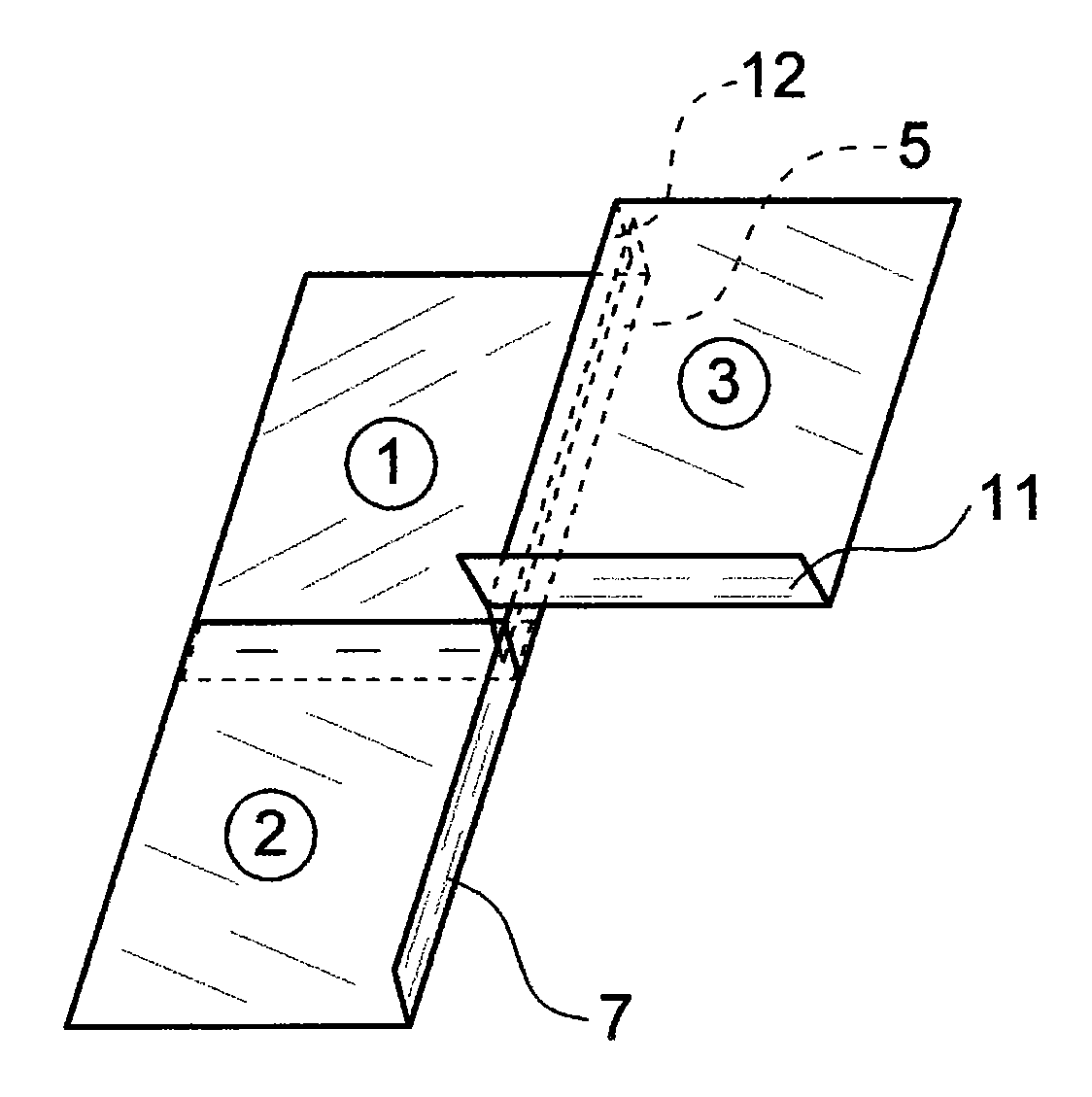
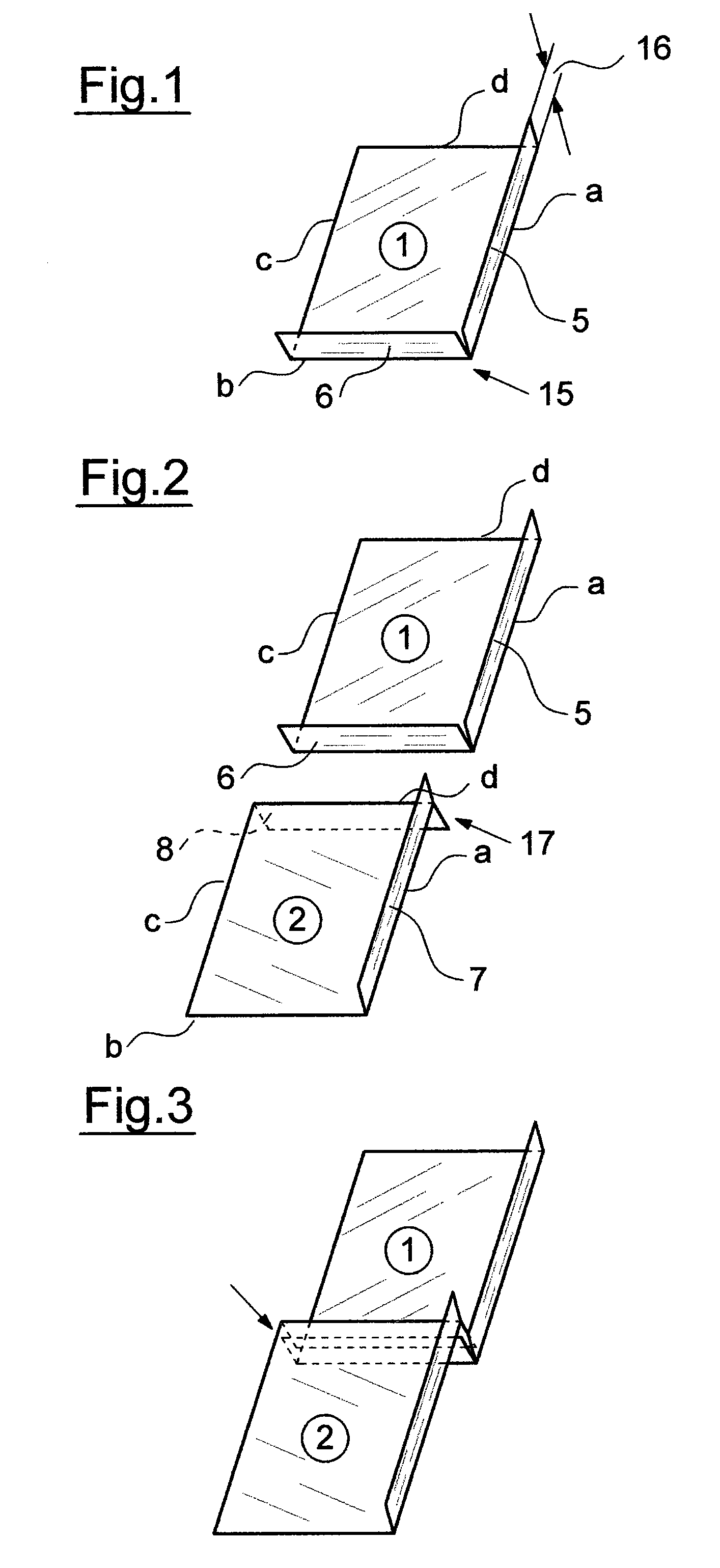
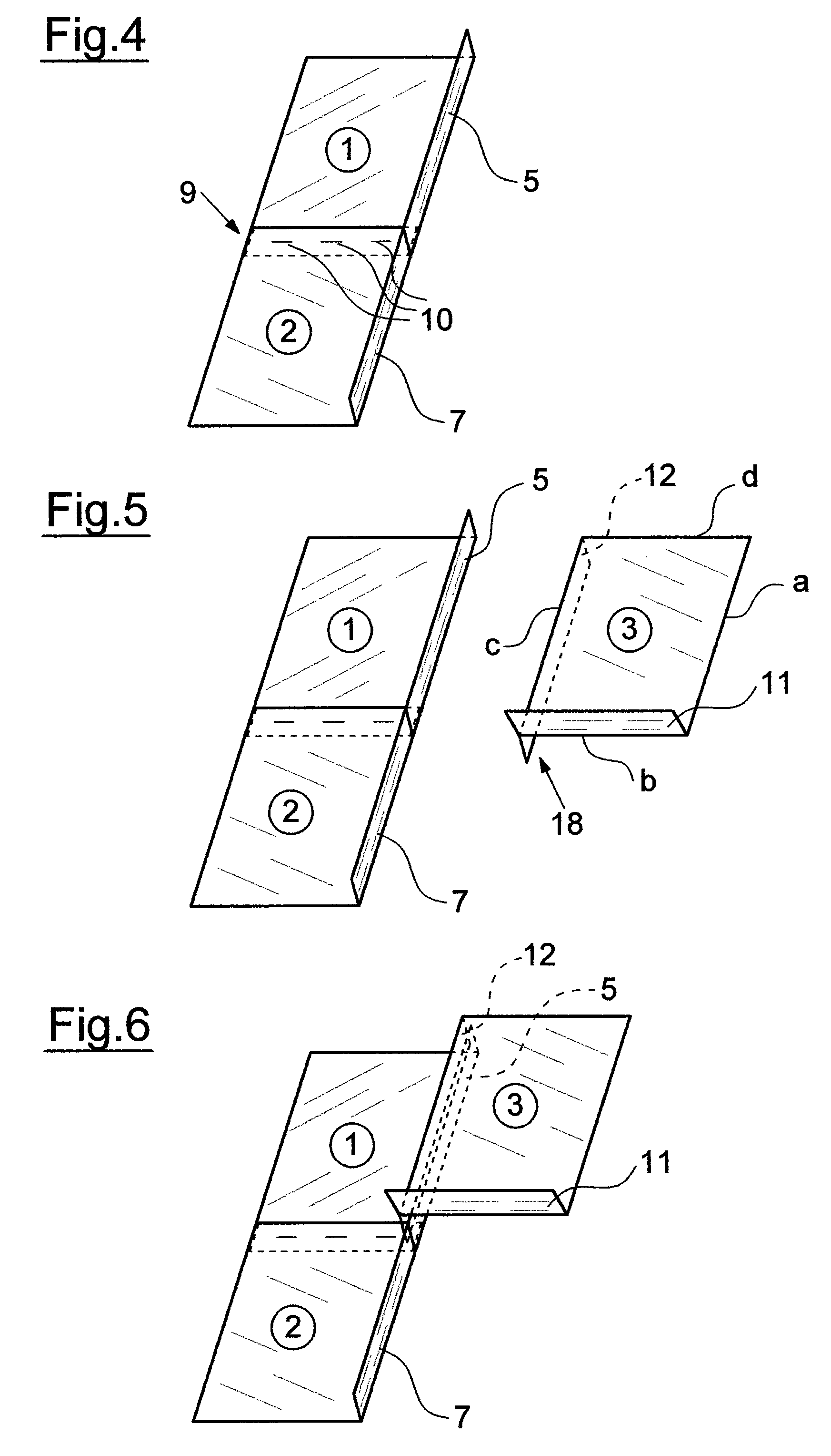
[0020]The basic configuration of a shield for a room or for a building is not shown in the drawing in detail. It consists of a multitude of mesh and grid sections 1-4, which are connected in an overlapping and conductive manner as shown in the drawings. They form a mesh or grid and completely surround the room or the building from all sides, from the ceiling, from the ground, and they are grounded at least in one point, preferably in many points.

[0021]In the area of doors and windows care must taken that the grid or mesh structure is realized in a similar manner, whereby in particular the tight and conductive alignment of the surfaces moveable relative to each other, typically the contact areas of window and door folds, is important. Here, the shield can be provided on the inside or on the outside or on both sides. For rooms the shield is preferably provided on the inside, for buildings the shield is preferably provided on the outside.

[0022]The basic configuration of a shield made f...


PUM


Abstract

An electromagnetic shield is provided for a room or for a building, including overlapping, conductively connected, and electrically conductive mesh or grid sections (1-4). The sections are grounded and folded in the overlapping area, where the folds of adjacent mesh or grid sections (1, 2) interlock like hooks in a cross section view.

Description

BACKGROUND OF THE INVENTION[0001]The invention relates to an electromagnetic shield for a room or for a building.[0002]Known electromagnetic shields are intended to block electromagnetic waves, which are typically used for wireless radio communication, from buildings or parts of buildings, and on the other hand they are used to assure that electromagnetic radiation from a room or from a building does not get outside. Typically, they are not suited to protect technical installations like nuclear power plants from a nuclear electromagnetic pulse (NEMP) or from another electromagnetic pulse with high amplitude (HEMP—high altitude electro magnetic pulse). Such an electromagnetic pulse typically occurs when a nuclear chain reaction is set off in the air, e.g. when an atomic or hydrogen bomb is exploded at ground level, but also through targeted punctual generation (HPM—high power microwave). The electromagnetic radiation generated thereby is strong enough to disturb or destroy all electr...

Claims


Application Information

Patent Timeline
Patent Type & Authority Patents(United States)
IPC IPC(8): H01R4/00H01R4/56H05K9/00
CPCH05K9/0003
Inventor KESSEL, WOLFGANG
Owner KESSEL WOLFGANG
Why Eureka
Try Eureka