Building incorporating a thermal insulation assembly and method of conserving energy

a technology of thermal insulation and building, applied in the field of building incorporating a thermal insulation assembly and a method of conserving energy, can solve the problems of wind and solar energy, low energy concentration and variable availability, and the tendency of water absorption to have a detrimental effect on the thermal insulation value of the material, so as to prevent a reduction of thermal efficiency and a deterioration of the material

Inactive Publication Date: 2009-08-18
FREEGEN RES
View PDF17 Cites 4 Cited by
  • Summary
  • Abstract
  • Description
  • Claims
  • Application Information

AI Technical Summary

Benefits of technology

[0010]According to another aspect of the present invention there is provided a method for conserving energy in a building incorporating a surface subject to a thermal gradient emitting from a building interior, comprising the step of applying to the surface a thermal insulation assembly, which thermal insulation assembly comprises: thermal insulation comprising first and second layers of insulation, one of the layers being positioned adjacent to the surface of the building; and an electrical heating element provided with means for connection to a source of electrical power and positioned within the thermal insulation between the first and second layers so as to extend substantially parallel to the surface.
[0013]Describing the operation of one preferred embodiment of the assembly from a cold start up: an electrical power source supplies energy to the heating element, at a rate equivalent to a very low Wattage per square metre of heating element, and the heating element is in contact with a thermal conductor that provides and even distribution of heat across the directional plane of the heating element. Heat is being released and flows into the inner and outer layers of thermal insulation. The insulation acts to restrain the flow of heat from the element and conductor. Restriction of the heat flow results in the temperature of the element and conductor increasing. A rising element and conductor temperature acts to cause an increase in the temperature level of a building surface, adjacent to and between the element and conductor and the building interior, as the heat contained within the building interior flows through the adjacent building surface and the assembly to the exterior, and is influenced by the escalating element and conductor temperature level. The rate of heat flow from the interior to the exterior is reducing as a result of the decreasing thermal gradient between the interior and element temperatures. A thermostatic controller acts to equalise the building interior temperature with the element temperature. When the temperature levels of the building interior, the adjacent building surface, the inner insulation layer and the element are equalised, then no thermal gradient occurs between the four zones. As heat requires a thermal gradient to flow, then under such a condition, a neutral thermal gradient is created that prevents the heat in the interior of the building flowing through the adjacent building surface into the inner insulation layer of the assembly. Likewise, heat flow from the element through the inner insulation layer to the adjacent building surface is prevented, thus preventing the electrical energy being supplied to the element providing heating to the building interior. Heat is flowing from the element through the outer insulation layer to the exterior atmosphere whenever a negative thermal gradient exists between these two zones. By this method, the assembly prevents heat outflow from the building interior and thereby improves the thermal insulation of the building interior.
[0025]Advantageously, the release of electrical energy as heat within the insulation supplies the latent heat of evaporation for such atmospheric water as may be absorbed by the insulation material. This provides a means of preventing a reduction of thermal efficiency and a deterioration of material, due to moisture absorption.

Problems solved by technology

A difficulty with the use of natural energy forms, such as wind and solar energy, is their relatively low energy concentration and variable availability.
In the context of buildings there are practical issues of scale for natural energy collectors, for instance wind turbines and solar PV (photovoltaic) panels.
Under the circumstances described, temperature variations between the insulation enclosure and the atmosphere outside may cause condensation.
One disadvantage of this atmospheric exposure is that most insulation materials exhibit some hygroscopic tendencies.
The absorption of water has a detrimental effect on the thermal insulation value of the material.
In terms of constructing a building this creates problems of the increased space required for the insulation and the material cost.
Another problem is the effect of moisture absorption on the lifespan of insulation materials.
Utilizing an energy supply, providing low Wattages per square metre of building surface area, for heating applications is relatively difficult.

Method used


Image

  • Building incorporating a thermal insulation assembly and method of conserving energy
  • Building incorporating a thermal insulation assembly and method of conserving energy
  • Building incorporating a thermal insulation assembly and method of conserving energy

Examples


Embodiment Construction

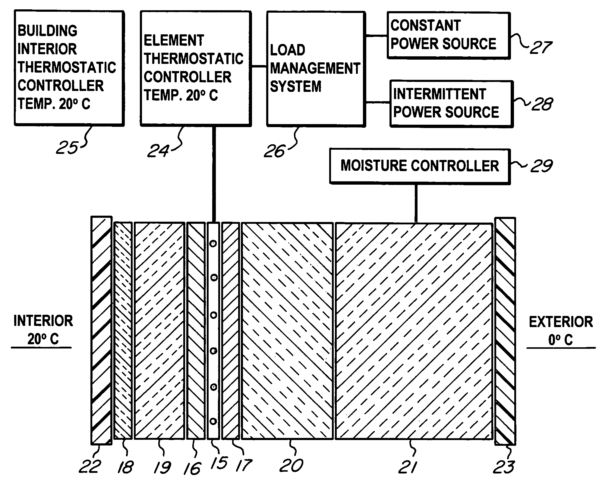
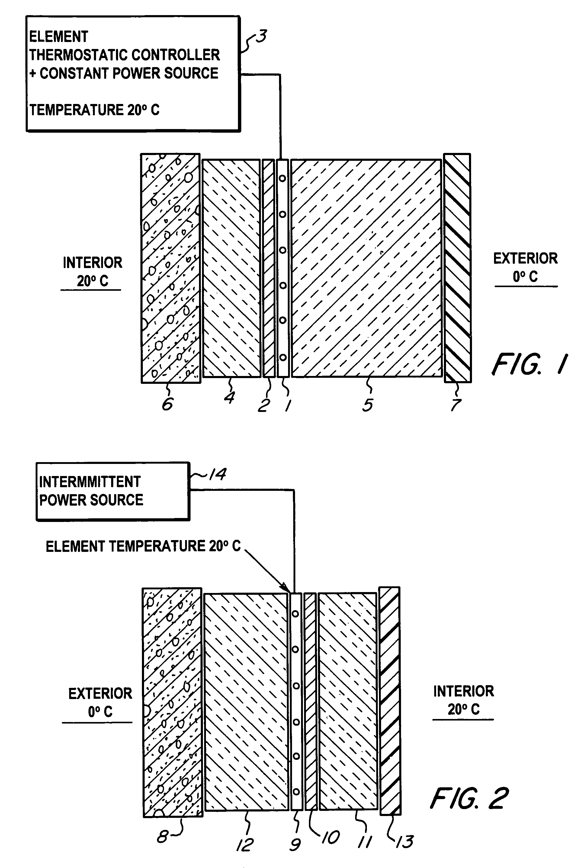
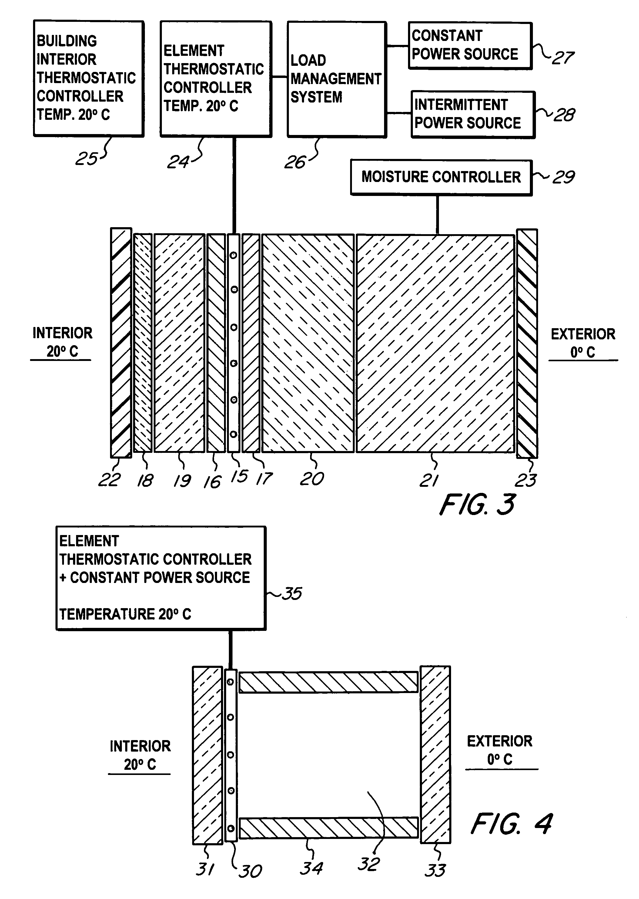
[0031]FIG. 1 illustrates a thermal insulation assembly comprising an electrical heating element 1 positioned longitudinally within thermal insulation and in thermal contact with a thermal conductor 2 providing an even distribution of heat in the directional plane of the element 1. An aluminium sheet is used as the thermal conductor 2. An electrical connection is provided from the element 1 to a thermostatic controller 3 switching to a constant electrical power source. An inner layer 4 and an outer layer 5 of thermal insulation thermally insulate the element 1. The insulating effectiveness of the inner layer 4 provides sufficient thermal isolation for the element 1 to be thermostatically controllable. The outer layer 5 is of high efficiency thermal insulation typically providing a U value in the range 0.400 to 0.005 Watts per square metre per degree Kelvin. The element 1 may be of any suitable kind, converting electrical energy into thermal energy and generally having an output of no...


PUM


Abstract

The performance of a thermal insulation for a building surface 6, subject to a thermal gradient emitting from the building interior, is enhanced by a neutral thermal gradient. For this purpose an electrical heating element 1 is adapted to release very low Wattages of thermal energy and is contained within an inner layer 4 and an outer layer 5 of thermal insulation. Adjusting the thermal efficiency of the insulation layers controls the magnitude of the thermal energy required to maintain the temperature of the element 1 at the equivalent temperature level to the building interior. The element 1 may be provided with a moisture controller and discharge sizeable quantities of thermal energy to dry moisture from the thermal insulation materials of the assembly.

Description

TECHNICAL FIELD OF THE INVENTION[0001]The present invention is related to a building incorporating a thermal insulation assembly and to a method of conserving energy.BACKGROUND OF THE INVENTION[0002]It is generally recognized that there is a global requirement to use more renewable energy, rather than energy from conventional fossil fuel sources. A difficulty with the use of natural energy forms, such as wind and solar energy, is their relatively low energy concentration and variable availability. In the context of buildings there are practical issues of scale for natural energy collectors, for instance wind turbines and solar PV (photovoltaic) panels. Taking as an example a residential property with either a 3 metre diameter wind turbine or 10 square metres of solar PV panels, the average electrical energy output would typically be in the range 200-400 Watts. Assuming the building has an outer surface area of 100 square metres then the available energy would be 2-4 Watts per square...

Claims


Application Information

Patent Timeline
Patent Type & Authority Patents(United States)
IPC IPC(8): H05B1/02F24D13/02H05B3/20
CPCE04B1/7608F24D13/02E06B3/67Y02B30/26Y02B30/00
Inventor GASKELL, CHRISTOPHER NORMAN
Owner FREEGEN RES
Why Eureka
Try Eureka