Electronic device

a technology of electronic devices and components, applied in the field of electronic devices, can solve the problems of increasing the labor of mounting each component, requiring a considerable physical space inside the equipment, and generating heat by the components, and achieve good thermal coupling

Inactive Publication Date: 2009-08-18
EMBRACO IND DE COMPRESSORES E SOLUCOES EM REFRIGERACAO LTDA
View PDF16 Cites 36 Cited by
  • Summary
  • Abstract
  • Description
  • Claims
  • Application Information

AI Technical Summary

Benefits of technology

[0015]The objective of the present invention is to provide a good thermal coupling between the electronic components and the environment, by means of an electronic device having electrical insulation characteristics, which does not need openings for passing metallic components that are responsible for conducting heat to the environment.
[0016]It is also an objective of the present invention to eliminate the necessity to use screws or other means for keeping the electronic components in contact with the heat dissipator.
[0017]Another objective of this invention is to eliminate the necessity to install specific components for electric insulation between the energized parts of the components and the dissipator exposed to the environment.
[0018]A further objective of this invention is to provide effective and simple dissipation of the heat generated in the circuit, substantially reducing the size of the device, facilitating its construction, avoiding the need for mechanical precision and decreasing the manufacture costs.

Problems solved by technology

Circuits used for controlling motors in general, (including hermitic compressors for cooling), use electronic components that experience energy losses during operation resulting in heat generation by the components.
Although this is a quite effective and is a widely used way of providing a thermal coupling, it requires an attachment means, for example a screw, clip or the like, so that a physical coupling can be made between the electronic component and the dissipator, which requires a considerable physical space inside the equipment.
Another drawback of this technique is that it requires added labor for mounting each component of the dissipator, entailing a high cost for this mounting process.
This is a very efficient way of transferring heat, but it requires a special construction for the dissipator that contains this cooling fluid, thus making it very expensive.
This technique requires an opening in the box that protects the equipment, resulting in complications for project, manufacture and mounting, and requiring effective solutions to avoid penetration of fluids into the equipment and to guarantee insulation between the parts electrically connected to the circuit and the dissipator, especially because the latter is accessible from the outside and may represent a risk to safety.
This configuration has the disadvantage of dissipating the heat generated by the assembly of electronic components only when the heat has already exceeded the envelope of this device, that is to say, the silicone plate is not in direct contact with the components, but rather with the envelope that contains them.
However, since this substance does not have electric-insulation characteristics, it does not come into direct contact with the electronic components nor with the printed-circuit board, and is thus limited to the contour defined by the polymeric film.
This construction requires various associated processes during the manufacture of this envelope, which increase its cost due to the need for added labor.
Another disadvantage is that, in addition to the thick metallic plate, the envelope has another protecting layer, which makes the release of heat to the environment difficult.
In order to overcome this drawback, a cooling system and the presence of connectors are described, which increases the cost and the physical space occupied by the envelope.

Method used


Image

  • Electronic device
  • Electronic device

Examples


Embodiment Construction

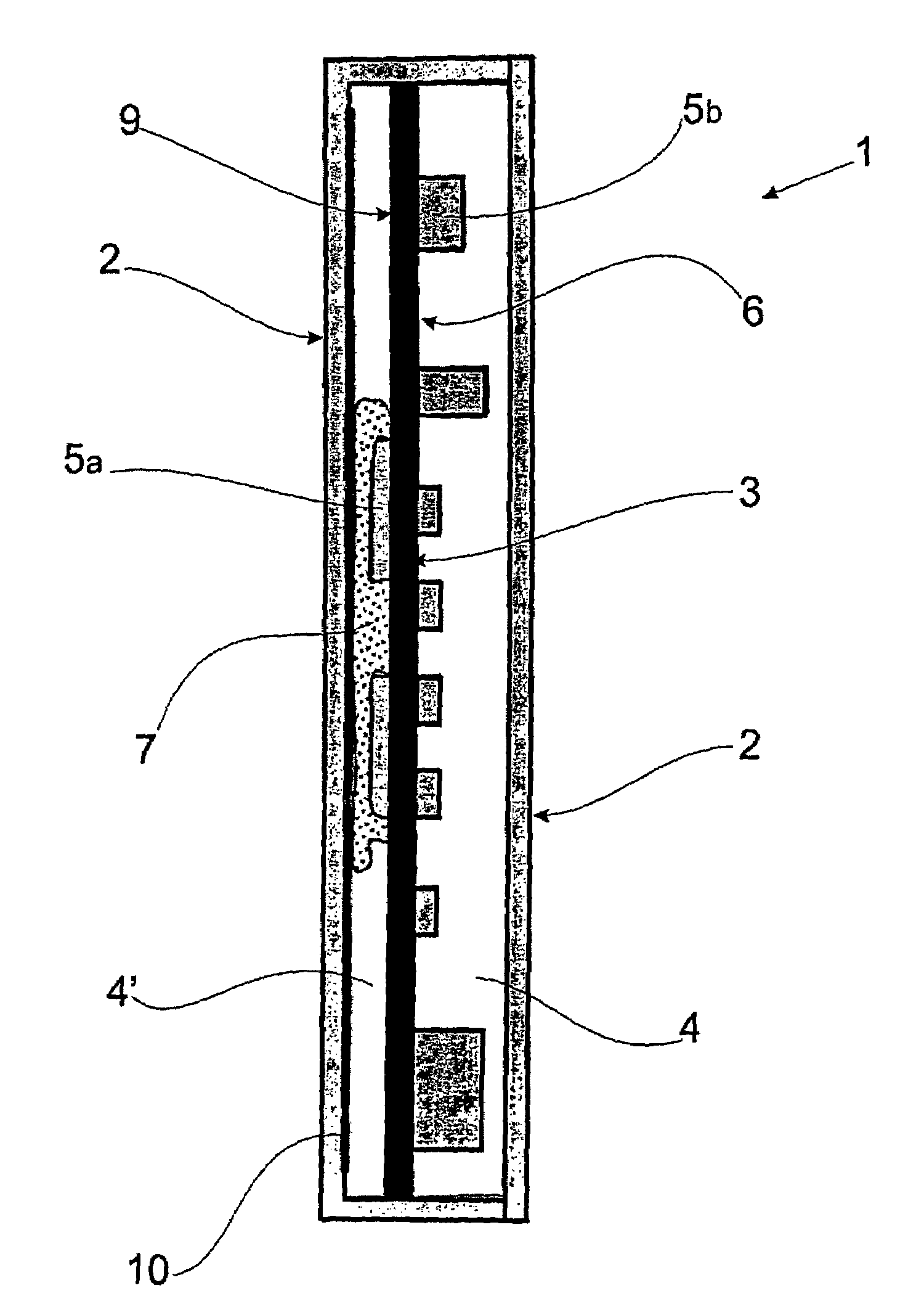
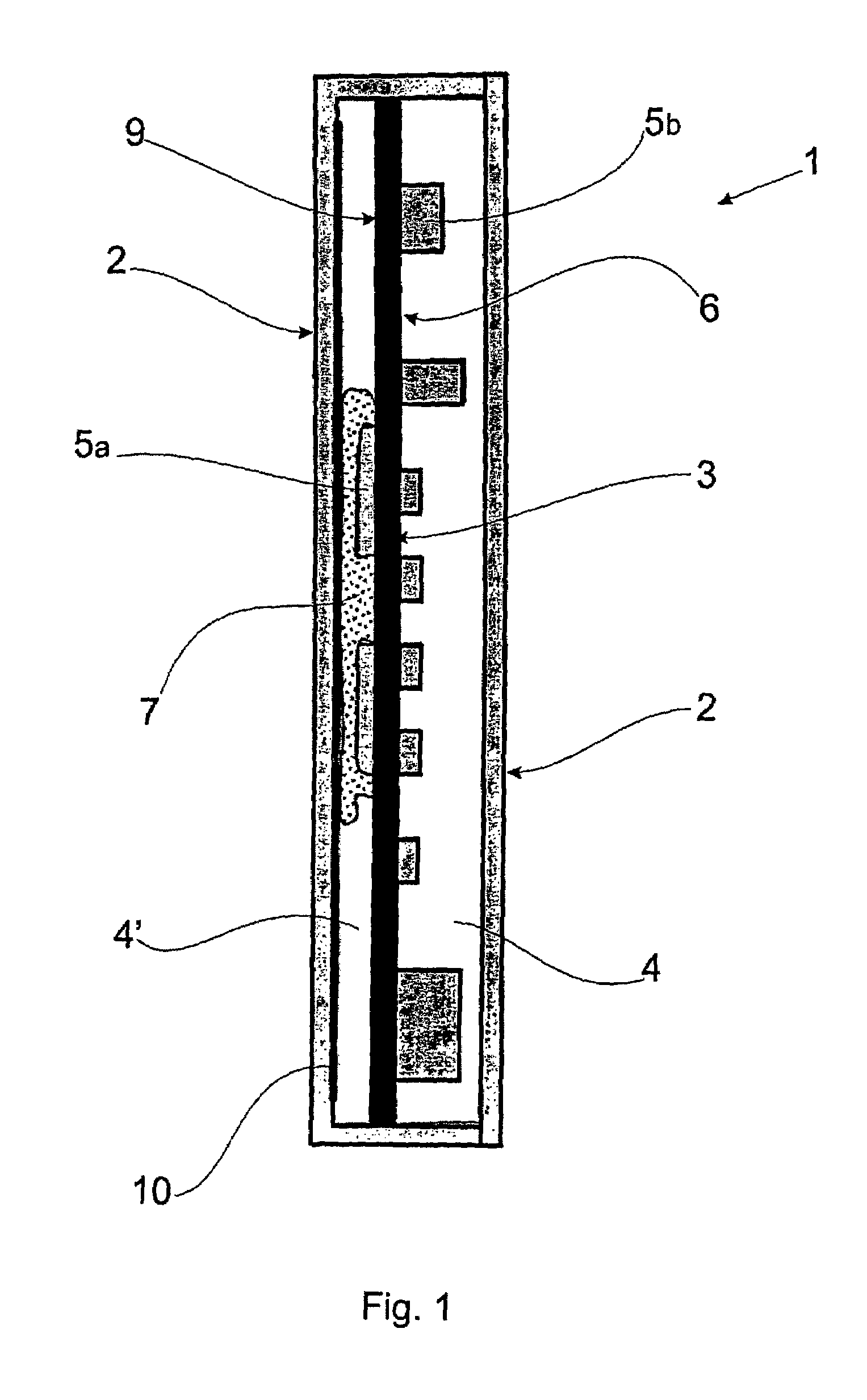
[0022]According to a preferred embodiment and as can be seen in FIG. 1, the electronic device 1 is formed by an envelope 2, a closed chamber 4, a dissipation chamber 4′, a printed-circuit board 3, electronic components 5a, 5b, a filling 7 and a dissipation film 10.

[0023]The envelope 2 is preferably formed from a rigid polymeric material and can assume different geometric shapes. The polymeric material imparts electric-insulation characteristics to the envelope 2.

[0024]The chamber 4 is delimited by the envelope 2 and represents the empty space formed inside the device 1. The printed-circuit board 3 provided with electronic components 5a, 5b, the filling 7 and the dissipation film 10 are inserted into the chamber 4.

[0025]The printed-circuit board 3 is positioned inside the device 1, so as to define a dissipation chamber 4′, which comprises the electronic components 5a, which are associated to the first surface 9 of the plate 3. The plate 3 has also electronic components 5b, associated...


PUM


Abstract

An electronic device is described, which comprises an envelope comprising a closed chamber and a printed-circuit board. The printed-circuit board is positioned in the chamber and defines a dissipation chamber. The printed-circuit board comprises at least one electronic device positioned in the dissipation chamber. The dissipation chamber comprises a filler simultaneously in contact with the electronic component, the printed-circuit board and a dissipation film.

Description

CROSS-REFERENCE TO RELATED APPLICATIONS[0001]This patent application is a continuation and claims priority to U.S. patent application Ser. No. 10 / 250,989, filed Nov. 12, 2003 now abandoned, and entitled An Electronic Device.BACKGROUND OF THE INVENTION[0002]1. Field of the Invention[0003]The present invention relates to an electronic device, simultaneously provided with heat dissipation medium and a heat insulation, used in motor-control circuits in general.[0004]2. Description of the Prior Art[0005]Circuits used for controlling motors in general, (including hermitic compressors for cooling), use electronic components that experience energy losses during operation resulting in heat generation by the components. There are various techniques of thermal coupling used today for providing transfer of this undesired heat to the environment, thereby avoiding overheating of the circuit, which may cause damage and / or reduction of the useful life of the electronic components.[0006]The better t...

Claims


Application Information

Patent Timeline
Patent Type & Authority Patents(United States)
IPC IPC(8): H05K7/20H01L23/40
CPCH05K7/20472H05K7/20454
Inventor SCHWARZ, MARCOS GUILHERME
Owner EMBRACO IND DE COMPRESSORES E SOLUCOES EM REFRIGERACAO LTDA
Why Eureka
Try Eureka