Optical coherence tomography system

a coherence tomography and optical coherence technology, applied in the field of optical coherence tomography system, can solve the problems of blood disrupting the representation, the vessel must remain sealed for at least 50 seconds, and the relatively long period of a live system

Inactive Publication Date: 2009-08-18
SIEMENS HEALTHCARE GMBH
View PDF4 Cites 115 Cited by
  • Summary
  • Abstract
  • Description
  • Claims
  • Application Information

AI Technical Summary

Benefits of technology

[0014]Because a plurality of signals can be obtained simultaneously and the fibers can be controlled mutually independently, the time needed to record images having a specific number of image elements is inversely proportional to the number of light conducting fibers and optical units. If, say, three independent fibers are used along with three optical units assigned thereto, then it will be possible in each case to record three signals simultaneously and thus reduce the length of time to record a cross-sectional image to one third or to produce three such cross-sectional images simultaneously, depending on the position of the fibers.
[0022]Said casing is beneficial particularly when the fibers are turned and moved longitudinally as it will fundamentally make it easier to move the fibers.
[0024]It will be of beneficial use for obtaining a three-dimensional data record if on or in the catheter an optical marking is provided that is discernible on the image. Said optical marking will make it possible to subsequently detect both the fiber's position from the image as well as, where applicable, the fiber's longitudinal movement. In a sensitive system, such as one comprising a plurality of fibers, a particular possible occurrence is for the fibers' mutual spatial relationship to change slightly. The optical marking will therein assist the signal processing unit in automatically correcting possible movements and displacements so that a reliable three-dimensional data record can be computed.
[0025]Instead of a separate optical marking, the imaging of the catheter as such, which is basically discernible on the image, can also be used in spatially assigning signals to each other. An optical marking is advantageous compared to the catheter faintly visible on the image on account only of the strength of the signal produced by said marking.

Problems solved by technology

What is problematic is that when blood vessels are shown in cross-sectional images the blood will disrupt the representation.
At the above-mentioned speed of retraction, in the case of a three-dimensional representation of a blood vessel the problem thus arises that if a 10-centimeter length has to be represented the vessel will have to remain sealed for at least 50 seconds.
That is a relatively long period for a live system.

Method used


Image

  • Optical coherence tomography system
  • Optical coherence tomography system
  • Optical coherence tomography system

Examples


Embodiment Construction

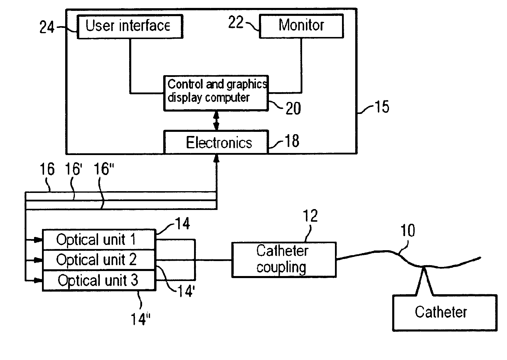
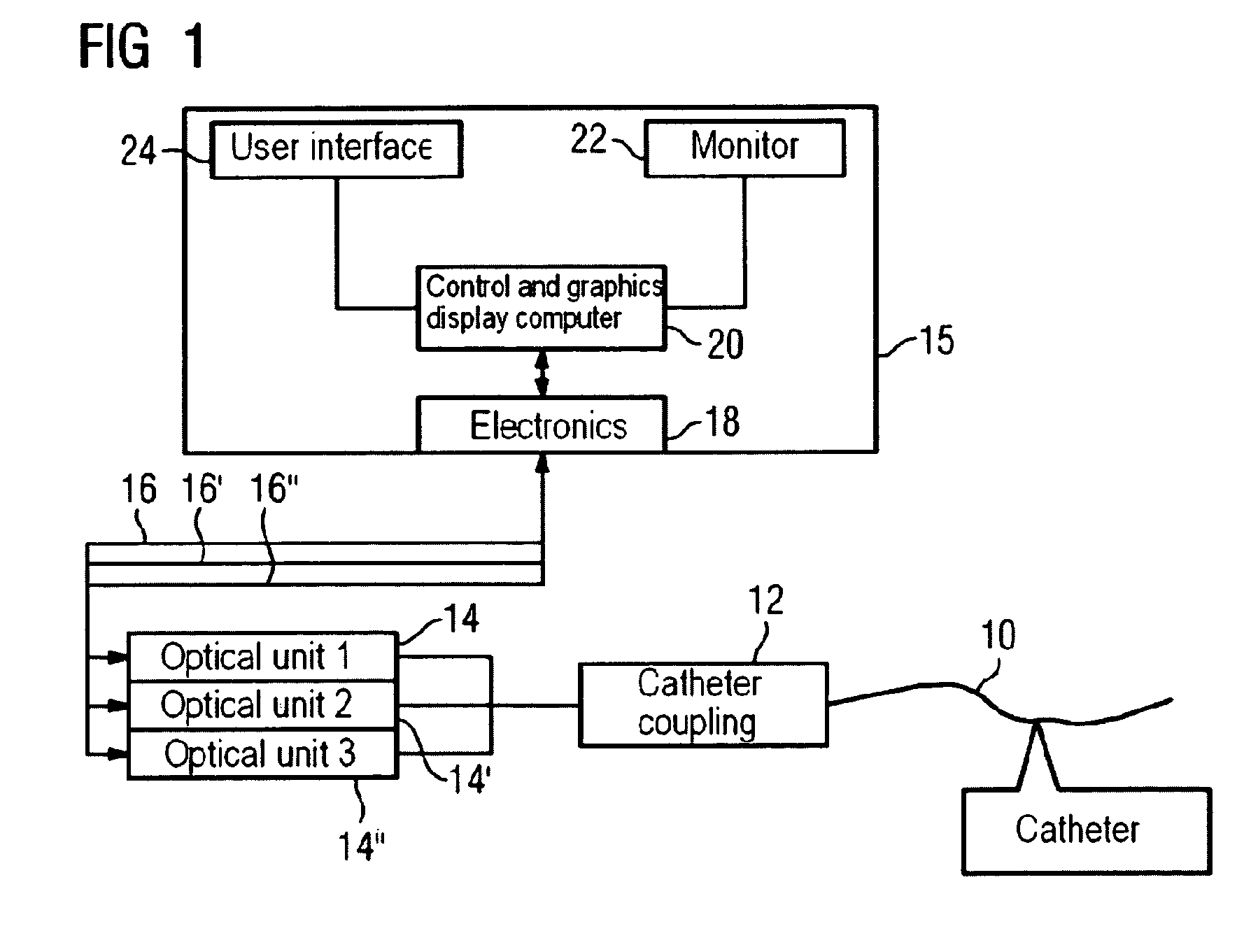
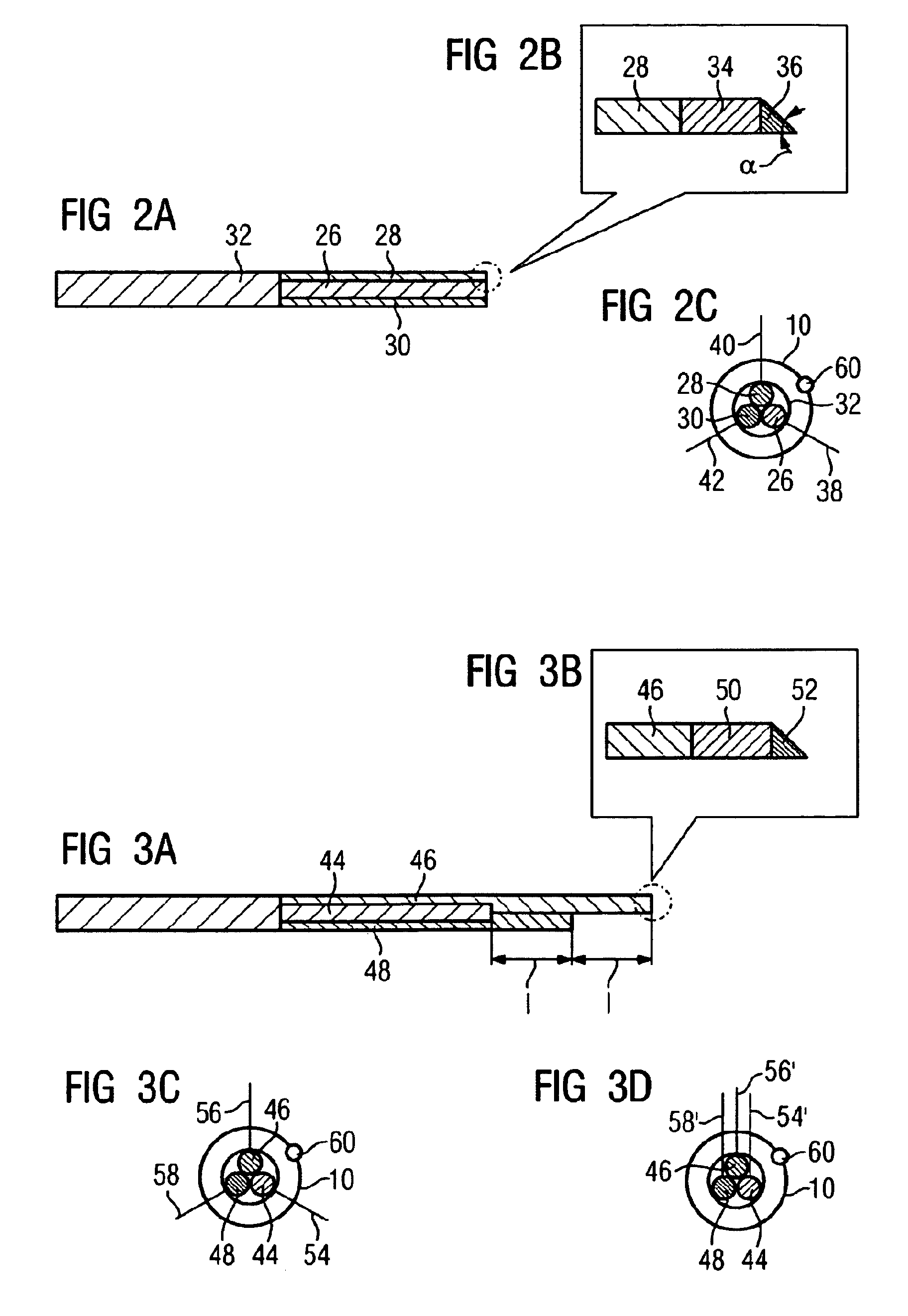
[0039]FIG. 1 shows the overall system employed for the invention.

[0040]The invention employs a single catheter 10. Located in said catheter 10 are three light conducting fibers (not shown in FIG. 1, but see FIG. 2 and FIG. 3). Each individual fiber is linked via a catheter coupling 12 to an associated optical unit. Shown in the figure are the optical unit 1, designated 14, that is linked to the first fiber, the optical unit 2, designated 14′, that is linked to the second fiber, and the optical unit 3, designated 14″, that is linked to the third fiber via the catheter coupling 12. The optical units 14, 14′, and 14″ are herein optical units conforming to the prior art for optical coherence tomography systems, which is to say Michelson interferometer units having a reference arm and an evaluation facility that includes, for example, a detector. The optical units 14, 14,′ and 14″ are independent to the effect that the individual fibers in the catheter 10 can receive light mutually indep...


PUM


Abstract

An optical coherence tomography system includes a catheter in which is arranged a plurality of light conducting fibers. It further includes a plurality of optical units. Light from the proximal end to the distal end and signals from the distal end to the proximal end can be transmitted simultaneously in different fibers. Time is saved through the simultaneous signal processing of signals from different fibers. That is advantageous particularly in the imaging, by means of coherence tomography, of blood vessels that have to be occluded for said imaging.

Description

CROSS REFERENCE TO RELATED APPLICATIONS[0001]This application claims priority of German application No. 10 2005 045 088.1 filed Sep. 21, 2005, which is incorporated by reference herein in its entirety.FIELD OF THE INVENTION[0002]The invention relates to an optical coherence tomography system having a catheter arranged with a plurality of light conducting fibers.BACKGROUND OF THE INVENTION[0003]Optical coherence tomography is still a very new imaging technology. An outline of optical coherence tomography is given in, for example, the article “Optical coherence tomography for ultrahigh resolution in vivo imaging” by James G. Fujimoto, in “Nature Biotechnology”, Volume 21, Number 11, November 2003, pp. 1361 ff. Variations are described in European patent EP 0 581 871 B1.[0004]Not only the surface of a sample is imaged in optical coherence tomography; in-depth imaging also takes place. While in the case of ultrasound systems a relevant signal can be assigned to a depth on the basis of c...

Claims


Application Information

Patent Timeline
Patent Type & Authority Patents(United States)
IPC IPC(8): A61B5/05
CPCA61B5/0066A61B5/6852G02B6/4249G02B6/04
Inventor CAMUS, ESTELLEMEISSNER, OLIVERREDEL, THOMAS
Owner SIEMENS HEALTHCARE GMBH
Why Eureka
Try Eureka