Deep well/long trench direct expansion heating/cooling system

Inactive Publication Date: 2009-08-25
EARTH TO AIR SYST
View PDF44 Cites 48 Cited by
  • Summary
  • Abstract
  • Description
  • Claims
  • Application Information

AI Technical Summary

Benefits of technology

[0015]It is an object of the present invention to further enhance and improve the efficiency of predecessor direct expansion geothermal heat exchange system designs by means of teaching certain line set sizes, distances, designs, depths, and lengths, including a long trench system design, certain vapor line coverings and moisturizing means, certain refrigerant operational pressures and type, certain pin restrictor sizes and locations, certain liquid line insulation lengths, certain containment pipe c

Problems solved by technology

While for new residential construction on relatively large lots, such designs can be well suited, the large surface area excavation requirements are often

Method used


Image

  • Deep well/long trench direct expansion heating/cooling system
  • Deep well/long trench direct expansion heating/cooling system
  • Deep well/long trench direct expansion heating/cooling system

Examples


Embodiment Construction

[0100]The following detailed description is of the best presently contemplated mode of carrying out the invention. The description is not intended in a limiting sense, and is made solely for the purpose of illustrating the general principles of the invention. The various features and advantages of the present invention may be more readily understood with reference to the following detailed description taken in conjunction with the accompanying drawings.

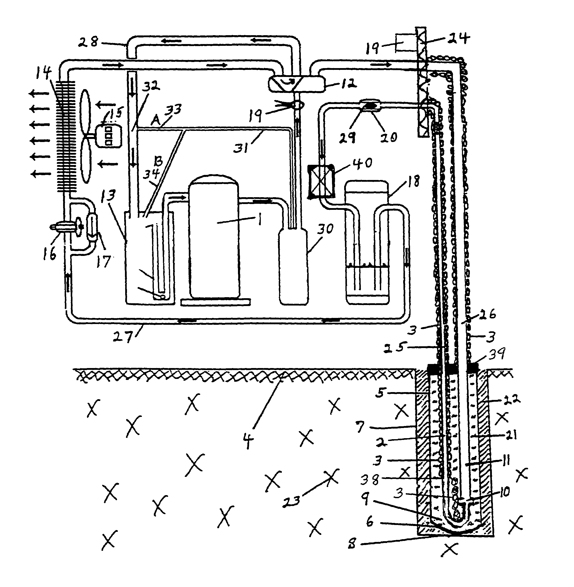
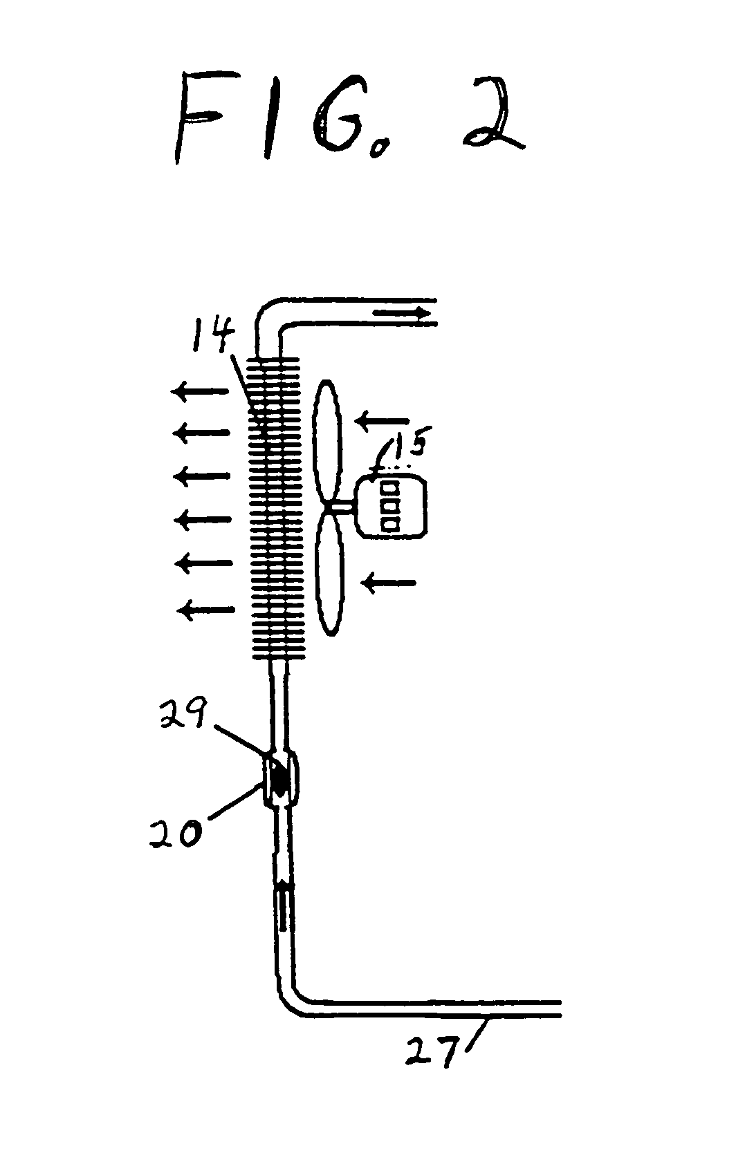
[0101]Referring now to the drawings in detail, where like numerals refer to like parts or elements, there is shown in FIG. 1 a side view of a simple version of a deep well direct expansion geothermal heat pump system, operating in a cooling mode.

[0102]A refrigerant fluid (not shown) is transported, by means of a compressor's 1 force and suction, inside a larger diameter un-insulated sub-surface refrigerant vapor transport / heat exchange line tube 11, which is located below the ground surface 4 within a heat conductive, watertight, poly...


PUM


Abstract

A direct expansion geothermal heat exchange system including certain line set sizes, distances, designs, depths, and lengths, including a long trench system design, certain vapor line coverings and moisturizing means, certain refrigerant operational pressures and type, certain pin restrictor sizes and locations, certain liquid line insulation lengths, certain containment pipe composition, pipe sizing with polyethylene, pipe antifreeze fill percentage, and pipe top sealing, a certain oil return safeguard procedure, certain interior heat exchanger design tonnages with predominate heating loads and with predominate cooling loads, a certain receiver type and capacity, an optional means of placing sub-surface refrigerant transport tubing within respective protective containment pipes, certain trench system and well/borehole system combinations, and certain trench creation means.

Description

CROSS-REFERENCES TO RELATED APPLICATIONS[0001]This application claims priority to U.S. Provisional Patent Application Ser. No. 60 / 456,335 filed Mar. 20, 2003, entitled “Deep Well / Long Trench Direct Expansion Heating / Cooling System”, which is hereby incorporated by reference in its entirety.[0002]A portion of the disclosure of this patent document contains material that is subject to copyright protection. The copyright owner has no objection to the facsimile reproduction by anyone of the patent document or the patent disclosure, as it appears in the Patent and Trademark Office patent file or records, but otherwise reserves all copyright rights whatsoever.BACKGROUND OF THE INVENTION[0003]The present invention relates to an improved sub-surface, or in-ground / in-water, direct expansion heat pump system incorporating a unique combination of various design feature improvements, component strengthening criteria, air handler sizing, sub-surface vertical heat exchange design improvements, su...

Claims


Application Information

Patent Timeline
IPC IPC(8): F25D23/12
CPCF25B30/06
Inventor WIGGS, B. RYLAND
Owner EARTH TO AIR SYST
Why Eureka
Try Eureka