Medical grafting methods and apparatus

a technology of grafting and medical devices, applied in the field of grafts, can solve the problems of high degree of invasiveness of these procedures, the requirement of general anesthesia for these procedures, and the inability to use sternotomy procedures on many patients, and achieve the effects of enhancing bio-utility, elasticity and distensibility

Inactive Publication Date: 2009-08-25
ST JUDE MEDICAL ATG
View PDF164 Cites 36 Cited by
  • Summary
  • Abstract
  • Description
  • Claims
  • Application Information

AI Technical Summary

Benefits of technology

[0019]The artificial grafts of this invention may be coated (in the case of tubular grafts, on the inside and / or outside) to still further enhance their bio-utility. Examples of suitable coatings are medicated coatings, hydrophylic coatings, smoothing coatings, collagen coatings, human cell seeding coatings, etc. The above-described preferred porosity of the graft covering helps the graft to retain these coatings. Additional advantages of the artificial grafts of this invention are their elasticity and distensibility (mentioned above), their ability to be deployed through tubes of smaller diameter (after which they automatically return to their full diameter), the possibility of making them modular, their ability to accept natural body organ tubing concentrically inside themselves, their ability to support development of an endothelial layer, their compatibility with MRI procedures, their ability to be made fluoroscopically visible, etc.

Problems solved by technology

Although the above-described sternotomy procedures are increasingly successful, the high degree of invasiveness of these procedures and the requirement of these procedures for general anesthesia are significant disadvantages.
Indeed, these disadvantages preclude use of sternotomy procedures on many patients.
Thoracostomy bypass procedures are less traumatic than sternotomy bypass procedures, but they are still too traumatic for some patients.
Also, the number of required bypasses may exceed the number of mammary arteries, thereby rendering thoracostomy procedures inadequate to fully treat many patients.
It is also substantially less traumatic than midline sternotomy, but it is still too traumatic for some patients.

Method used


Image

  • Medical grafting methods and apparatus
  • Medical grafting methods and apparatus
  • Medical grafting methods and apparatus

Examples


Embodiment Construction

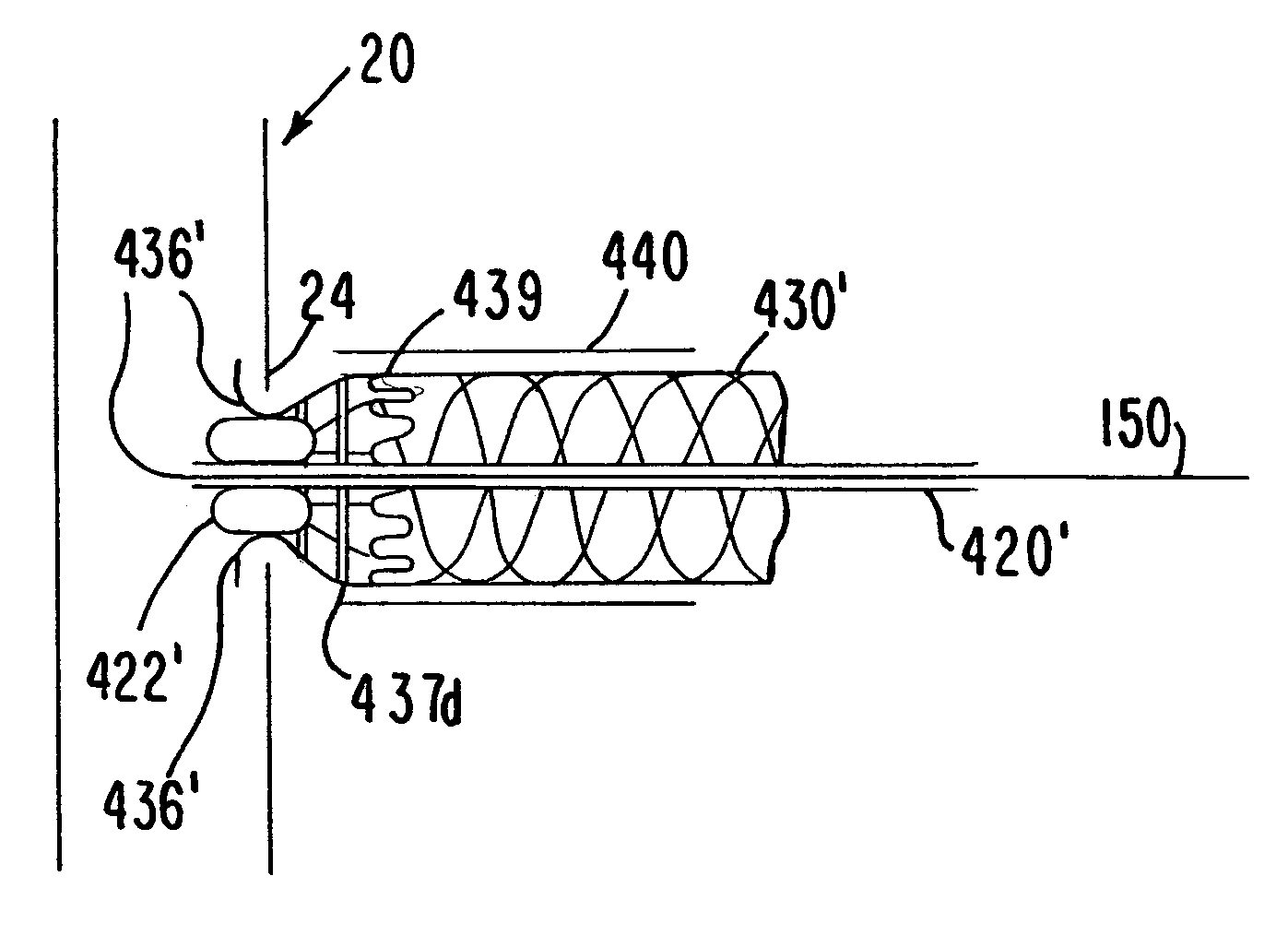
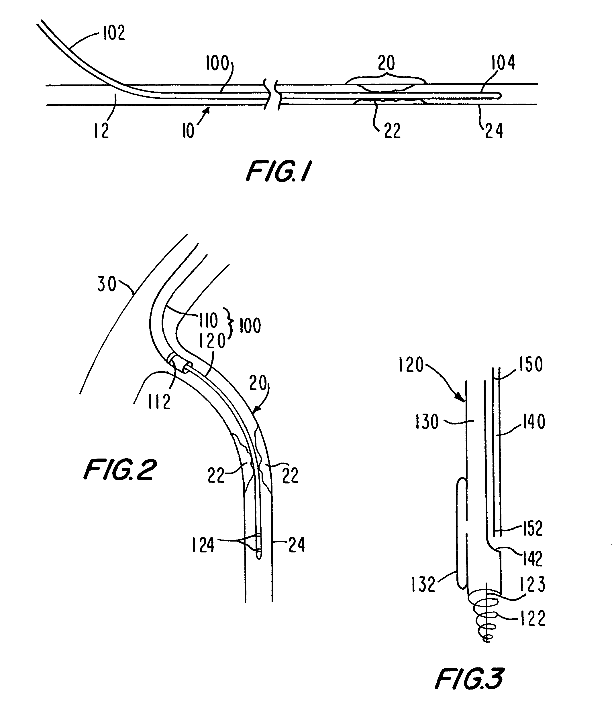
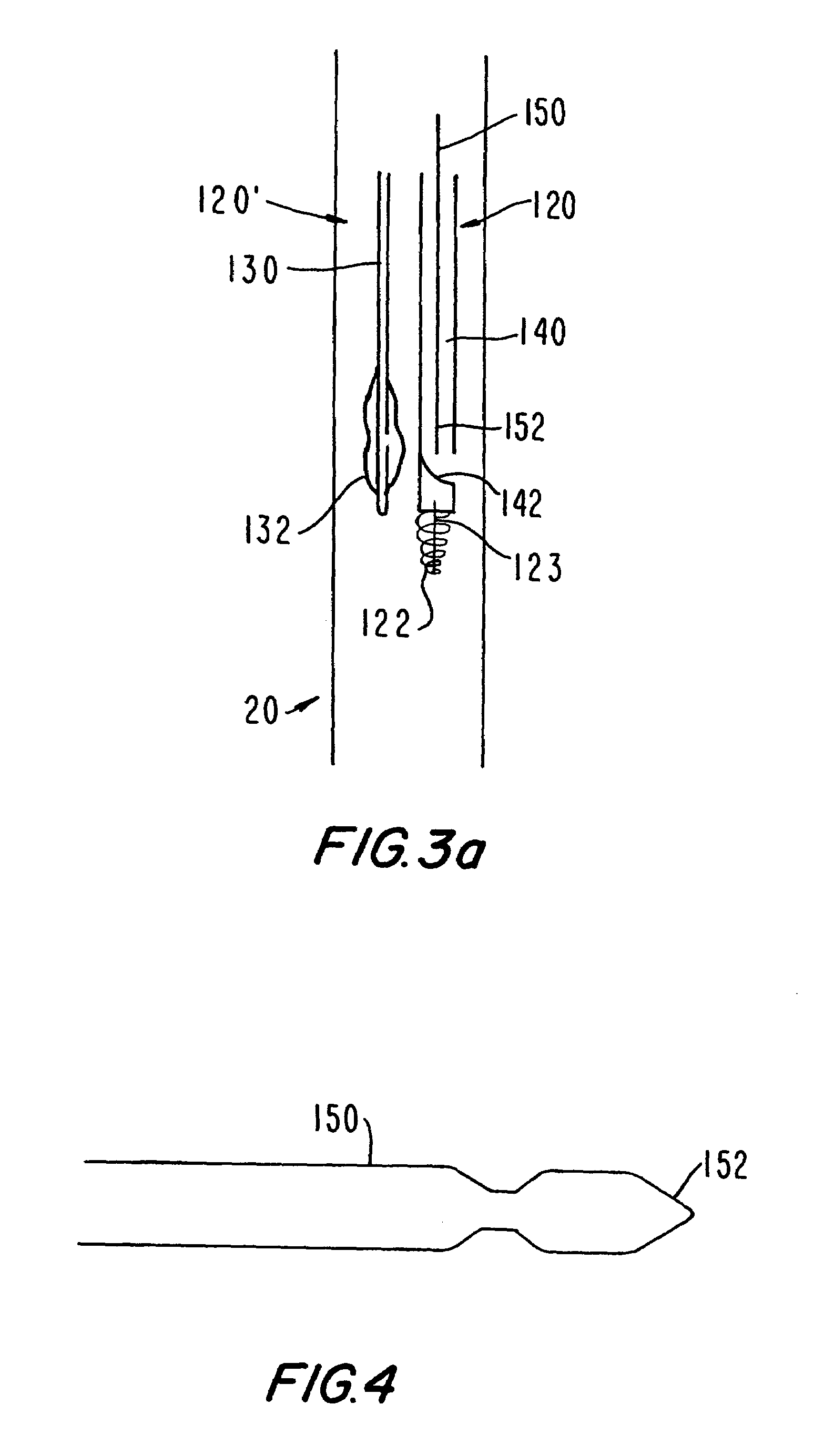
[0082]Because the present invention has a number of different applications, each of which may warrant some modifications of such parameters as instrument size and shape, it is believed best to describe certain aspects of the invention with reference to relatively generic schematic drawings. To keep the discussion from becoming too abstract, however, and as an aid to better comprehension and appreciation of the invention, references will frequently be made to specific uses of the invention. Most often these references will be to use of the invention to provide a bypass around an occlusion or obstruction (generically referred to as a narrowing) in a patient's coronary artery, and in particular a bypass from the aorta to a point along the coronary artery which is downstream from the coronary artery narrowing. It is emphasized again, however, that this is only one of many possible applications of the invention.

[0083]Assuming that the invention is to be used to provide a bypass from the ...


PUM


Abstract

Methods and apparatus for delivering and installing a new length of tubing between two sections of a patient's existing body organ tubing and at least partly outside of that existing structure. For example, the new length of tubing may be for the purpose of providing the patient with a coronary bypass. The new tubing may be an artificial graft, a natural graft (harvested elsewhere from the patient), or both. The new tubing is delivered to and installed at the operative site primarily by working through the patient's existing tubular body organ structure. This avoids the need for any significant surgery on the patient. The artificial grafts may have shapes other than tubular. Certain procedural and apparatus aspects of the invention have uses other than in connection with grafting in general or tubular grafting in particular.

Description

CROSS REFERENCE TO RELATED APPLICATIONS[0001]This application is a continuation of U.S. patent application Ser. No. 10 / 090,121, filed Feb. 28, 2002 (now abandoned), which was a continuation of U.S. patent application Ser. No. 09 / 955,244, filed Sep. 17, 2001 (now abandoned), which was a continuation of U.S. patent application Ser. No. 09 / 323,181, filed May 28, 1999 (now U.S. Pat. No. 6,302,905), which was a continuation of U.S. patent application Ser. No. 08 / 745,618, filed Nov. 7, 1996 (now U.S. Pat. No. 5,976,178). All of these prior applications are hereby incorporated by reference herein in their entireties.BACKGROUND OF THE INVENTION[0002]This invention relates to grafts for use in the repair, replacement, or supplement of a medical patient's natural body organ structures or tissues. The invention also relates to methods for making graft structures. The invention further relates to methods and apparatus for delivering a graft to an operative site in a patient, and for installing ...

Claims


Application Information

Patent Timeline
Patent Type & Authority Patents(United States)
IPC IPC(8): A61B17/08A61B1/005A61B17/11A61B17/00A61B17/22A61B17/28A61B17/32A61B19/00A61F2/00A61F2/06A61F2/82A61F2/90A61M25/00A61M25/01A61M25/09
CPCA61B1/0058A61B17/221A61B17/32056A61F2/06A61F2/064A61F2/07A61F2/954A61F2/958A61M25/0041A61M25/0133A61M25/0147A61M25/0152Y10S623/903A61B17/11A61B17/1114A61B2017/003A61B2017/1107A61B2017/1135A61B2017/1139A61B2017/2212A61B2017/2939A61B2019/5206A61B2019/5217A61F2/90A61F2/95A61F2002/061A61F2002/065A61F2002/3008A61F2002/30092A61F2002/826A61F2002/8486A61F2210/0014A61F2240/001A61F2250/0098A61M25/0108A61M25/04A61M25/09025A61M2025/0293A61M2025/1052A61B17/0057A61B2090/3614A61B2090/306
Inventor GOLDSTEEN, DAVID S.BACHINSKI, THOMAS J.MAZZOCCHI, RUDYSULLIVAN, DANIEL J.
Owner ST JUDE MEDICAL ATG
Why Eureka
Try Eureka