CMP retaining ring

a technology of retaining rings and retaining rings, applied in the field of retaining rings, can solve problems such as unsatisfactory changes in dimensions, and achieve the effects of reducing or eliminating deformation, reducing the compressibility of retaining rings, and reducing the wear resistance and elasticity of the base portion

Inactive Publication Date: 2007-09-27
BURNS JOHN +4
View PDF12 Cites 30 Cited by
  • Summary
  • Abstract
  • Description
  • Claims
  • Application Information

AI Technical Summary

Benefits of technology

[0010] An advantage of an embodiment of the invention is flexural rigidity provided by the ceramic or ceramic-filled polymeric material that comprises the backbone portion of the retaining ring. This rigidity reduces or eliminates deformation caused by the attachment of the retaining ring and reduces the compressibility of the retaining ring. Deformation and compressibility of the ring can lead to an uneven distribution of force across the ring, which causes undesired changes in dimensions.
[0011] Another advantage of an embodiment of the present invention is the wear resistance and elasticity of the base portion of the retaining ring. Embodiments of the present invention provide a durable yet flexible material that prevents chipping or cracking of the substrate edge where it is supported by the ring while reducing wear on the ring where it contacts the polishing pad.
[0012] Another advantage of an embodiment of the present invention is increased bond strength between the overmolded base portion and backbone portions. The circular ribs created in the bonding portion of the base portion or backbone portion of the retaining ring allow for a solid bond to be created when the other portion is overmolded onto it. In embodiments utilizing injection molding, thinner ribs and walls can be created which provide increased bonding and strength.
[0013] Another advantage of an embodiment of the present invention is ease of application of the polishing slurry during the polishing process. The channels dispersed around the outside of the retaining ring base portion facilitate the transport of slurry to and from the substrate. The divergent openings to the channels on the inside and outside of the ring and between adjacent pads or foil shaped pads facilitates the transport of slurry to and from the substrate.
[0014] Another advantage of an embodiment of the present invention is decreased cost and maintenance. The retaining ring is durable and has to be replaced less often due to its rigid upper portion and wear resistant lower portion. The injection molding and overmolding processes used to create the retaining ring are also simple and inexpensive processes. In addition, by eliminating metal from all or a part of the retaining ring in embodiments of the invention, corrosion and metal particle contamination from abraded particles can be significantly reduced or eliminated when the retaining ring is exposed to acidic or other corrosive polishing chemistries.

Problems solved by technology

Deformation and compressibility of the ring can lead to an uneven distribution of force across the ring, which causes undesired changes in dimensions.

Method used


Image

  • CMP retaining ring
  • CMP retaining ring
  • CMP retaining ring

Examples


Embodiment Construction

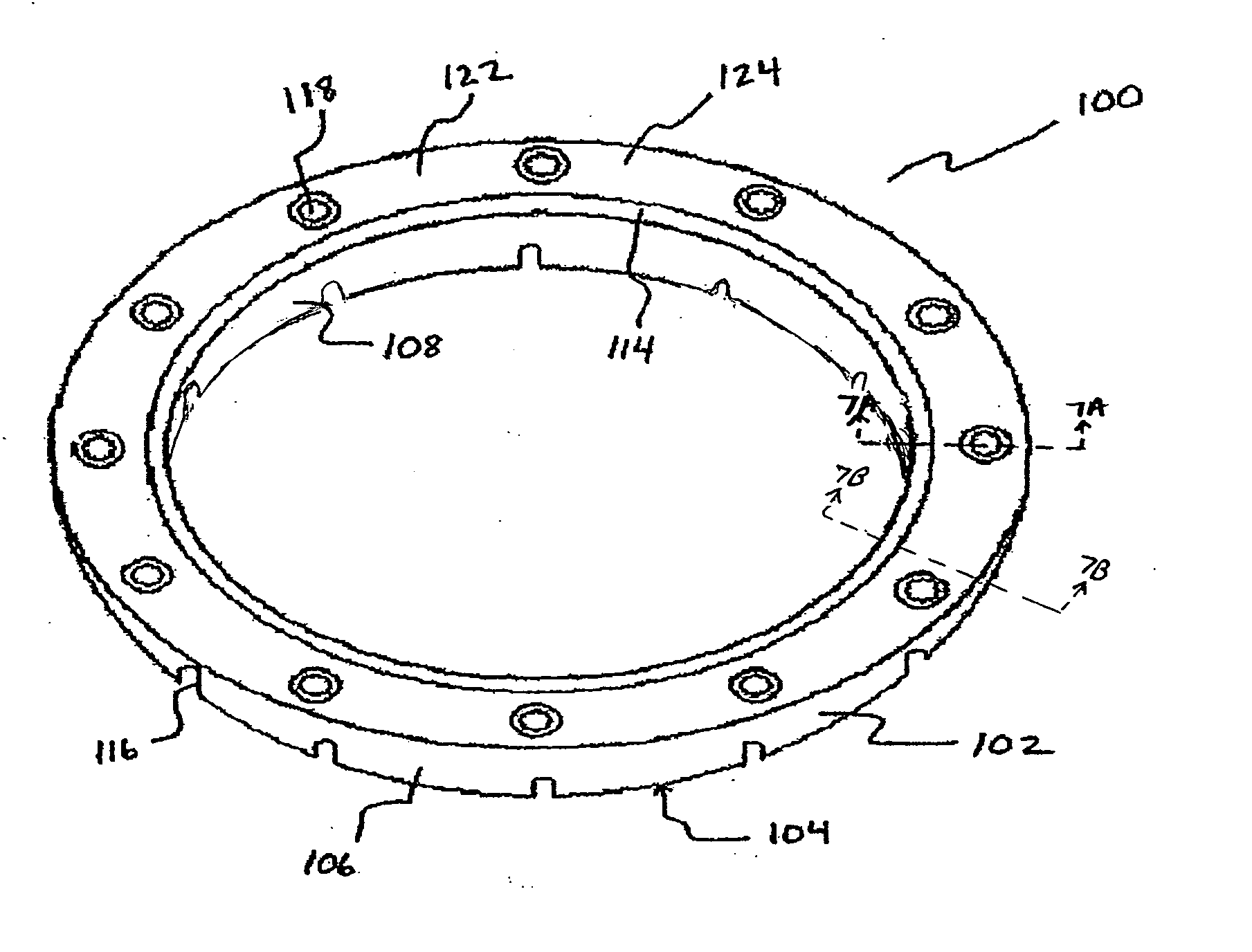
[0052] Referring to FIG. 1, there can be seen a CMP retaining ring 100 according to an embodiment of the present invention. Retaining ring 100 comprises a lower or base portion 102 and an upper or backbone portion 122.

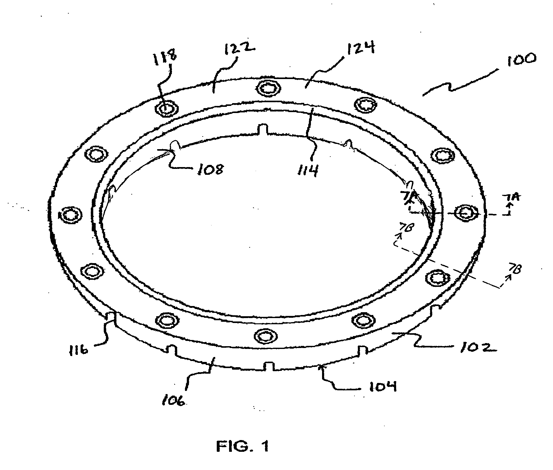
[0053] Referring now to FIG. 2 and FIG. 4, a separated view of lower base portion 102 according to an embodiment of the present invention can be seen. Base portion 102 is generally defined by a flat bottom surface 104, an outer surface 106, an inner surface 108, an upper rim 114, and a recessed portion 120. Recessed portion 120 further includes a plurality of circular ribs 110 and bosses 112 with threaded insert holes 118. Ribs 110 serve to create a solid bond when upper backbone portion is overmolded onto base portion and provide strength to the retaining ring by preventing twisting or bending of the ring 100. Base portion 102 additionally includes channels or grooves 116 extending from outer surface 106 to inner surface 108. Ribs 110 are axial with respect to retain...


PUM

PropertyMeasurementUnit
angleaaaaaaaaaa
heightaaaaaaaaaa
heightaaaaaaaaaa

Abstract

An improved chemical mechanical polishing retaining ring. A representative embodiment comprises a base portion made from a wear-resistant plastic material, and an upper portion, or backbone portion, made from a stiffer and more wear resistant material. One of the base or backbone portion is preferably overmolded onto the other. The base portion can be generally defined by a flat pad-contacting surface, an outer surface, and an inner surface. The base portion can additionally include channels extending from the outer surface to the inner surface to facilitate transfer of slurry to and from the substrate to be polished during the process. One or both of the base portion or backbone portion further includes a plurality of circular ribs that serve to create additional bonding surface with the overmolded material. The retaining ring may additionally includes a plurality of bosses with threaded insert holes by which the retaining ring is attached to a chemical mechanical polishing system.

Description

PRIORITY APPLICATION [0001] This application claims priority to U.S. Provisional Patent Application No. 60 / 684,151, filed May 24, 2005, of the same title, the disclosure of which is hereby incorporated by reference in its entirety, and U.S. Provisional Patent Application No. 60 / 765,995, filed Feb. 6, 2006, of the same title, the disclosure of which is hereby incorporated by reference in its entirety.FIELD OF THE INVENTION [0002] The present invention relates to a retaining ring for holding semiconductor wafers in a chemical mechanical polishing apparatus. BACKGROUND OF THE INVENTION [0003] Integrated circuits can be formed on semiconductor substrates, particularly silicon wafers, by the sequential deposition of conductive, semiconductive and insulative layers on the wafer. Circuitry features can be etched on after each layer is deposited. After a series of layers have been deposited and etched, the uppermost surface of the substrate can become increasingly non-planar. Non-planar sur...

Claims


Application Information

Patent Timeline
Patent Type & Authority Applications(United States)
IPC IPC(8): H01R3/00B24B37/32
CPCY10T29/49826B24B37/32B24B37/00H01L21/304
Inventor BURNS, JOHNFULLER, MATTHEW A.FORBES, MARTIN L.KING, JEFFERY J.SMITH, MARK V.
Owner BURNS JOHN
Why Eureka
Try Eureka