Surface acoustic wave device and communication device

a surface acoustic wave and communication device technology, applied in piezoelectric/electrostrictive/magnetostrictive devices, piezoelectric/electrostriction/magnetostriction machines, electrical equipment, etc., can solve the problems of unbalanced input-balanced output type surface acoustic wave filter, unbalanced input-balanced output, input-unbalanced output, etc., to achieve high sensitivity and improve balan

Inactive Publication Date: 2009-08-25
KYOCERA CORP
View PDF10 Cites 9 Cited by
  • Summary
  • Abstract
  • Description
  • Claims
  • Application Information

AI Technical Summary

Benefits of technology

[0015]This invention is directed to offer a surface acoustic wave device that provides improvement in balance (amplitude balance and phase balance) of a balanced type surface acoustic wave filter. This invention is also directed to offer a communication device having a high sensitivity.

Problems solved by technology

The unbalanced input-balanced output type surface acoustic wave filter means a surface acoustic wave filter having an unbalanced input and a balanced output.
The balanced input-unbalanced output type surface acoustic wave filter means a surface acoustic wave filter having a balanced input and an unbalance output.
On the other hand, the unbalanced input or the unbalanced output means that a signal is inputted or outputted as an electric potential on a single line against a ground electric potential.
However, the conventional balanced type surface acoustic wave filter is poor in balance.
Even with this structure, however, the amplitude balance and the phase balance are not good enough.
However, the amplitude balance and the phase balance of a balanced type surface acoustic wave filter of the structure mentioned above are not good because a polarity of outermost finger of the middle IDT electrode and a polarity of outermost finger of the IDT electrode adjacent the middle IDT electrode differ between left and right and thus parasitic capacitances formed at balanced signal terminals differ from each other.
In addition, communication devices using the conventional balanced type surface acoustic wave devices have been not satisfactory in sensitivity.

Method used


Image

  • Surface acoustic wave device and communication device
  • Surface acoustic wave device and communication device
  • Surface acoustic wave device and communication device

Examples


first embodiment

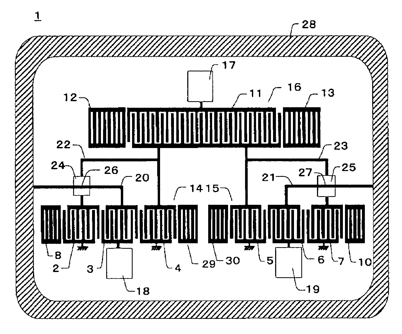
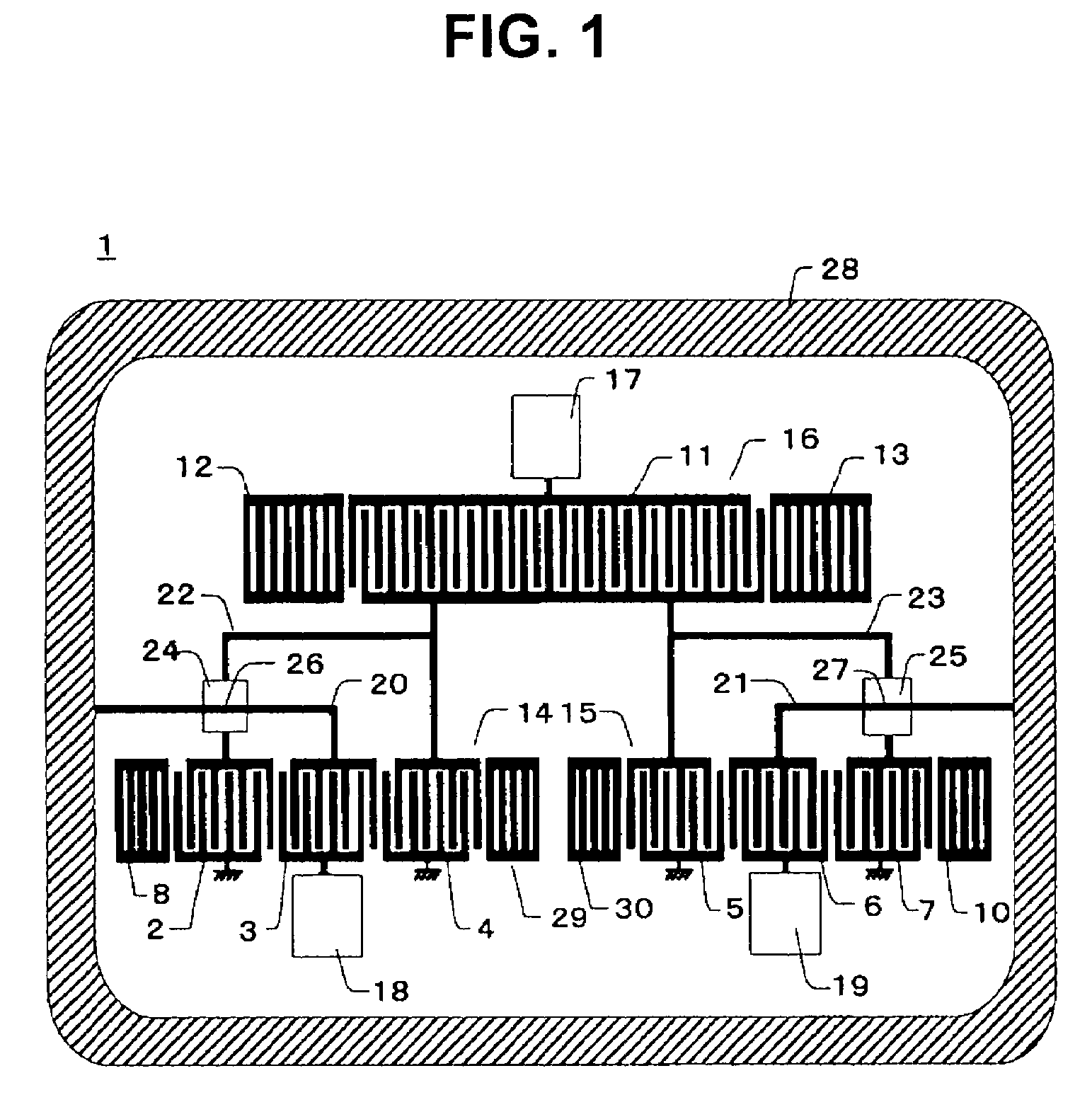
[0090]An example of manufacturing and evaluation of the surface acoustic wave device according to the first embodiment shown in FIG. 1 will be described in detail.

[0091]Fine electrode patterns made of an alloy of 99 weight % Al and 1 weight % Cu and constituting the first and second surface acoustic wave elements 14 and 15 were formed on a piezoelectric substrate (a mother substrate that is to be divided into a plurality of individual substrates) 1 made of 38.7° rotated Y-cut X-propagation single crystalline LiTaO3. The electrode patterns were formed by photolithography using a sputtering apparatus, a stepper and an RIE (Reactive Ion Etching) apparatus.

[0092]First, the piezoelectric substrate 1 was ultrasonically cleaned using acetone, isopropyl alcohol or the like to remove organic substances. After drying the piezoelectric substrate 1 sufficiently in a clean oven, a film of metal layer to make the electrodes was formed. The metal layer was formed by the sputtering apparatus using ...

second embodiment

[0107]An example of manufacturing and evaluation of the surface acoustic wave device according to the second embodiment shown in FIG. 4 will be described in detail.

[0108]Fine electrode patterns made of an alloy of 99 weight % Al and 1 weight % Cu were formed on a piezoelectric substrate (a mother substrate that is to be divided into a plurality of individual substrates) 101 made of 38.7° rotated Y-cut X-propagation single crystalline LiTaO3.

[0109]The electrode patterns were formed by photolithography using a sputtering apparatus, a stepper and an RIE apparatus.

[0110]First, the piezoelectric substrate 101 was ultrasonically cleaned using acetone, isopropyl alcohol or the like to remove organic substances. After drying the piezoelectric substrate 101 sufficiently in a clean oven, a film of metal layer to make the electrodes was formed. The metal layer was formed by the sputtering apparatus using the alloy of 99 weight % Al and 1 weight % Cu as material. A thickness of the metal layer ...


PUM


Abstract

A surface acoustic wave device includes front stage and rear stage surface acoustic wave elements, a signal wiring connecting between the front stage and rear stage surface acoustic wave elements, a reference potential wiring connected with the rear stage surface acoustic wave element and a capacitor made of an insulator interposed between the signal wiring and the reference potential wiring. A surface acoustic wave device includes a front stage surface acoustic wave resonator, a rear stage surface acoustic wave element, a signal wiring connecting between the front stage surface acoustic wave resonator and the rear stage surface acoustic wave element, a reference potential wiring connected with the rear stage surface acoustic wave element and a capacitor made of an insulator interposed between the signal wiring and the reference potential wiring. A communication device includes the surface acoustic wave device described above, a receiver circuit or a transmitter circuit.

Description

CROSS-REFERENCE TO RELATED APPLICATIONS[0001]The present application claims priority under 35 U.S.C. §119 to Japanese Patent Applications No. 2006-102499, filed Apr. 3, 2006, and No. 2006-102500, filed Apr. 3, 2006, entitled “SURFACE ACOUSTIC WAVE DEVICE AND COMMUNICATION DEVICE.” The contents of these applications are incorporated herein by reference in their entirety.BACKGROUND OF THE INVENTION[0002]1. Field of the Invention[0003]This invention relates to a surface acoustic wave device such as a surface acoustic wave filter or a surface acoustic wave resonator and a communication device equipped with the surface acoustic wave device used in a mobile communication device such as a mobile phone or the like.[0004]2. Description of the Related Art[0005]The surface acoustic wave filter has been widely used as a frequency selection filter used in an RF (Radio Frequency) stage in the mobile communication devices such as a mobile phone and an automobile telephone. In order to reduce a siz...

Claims


Application Information

Patent Timeline
Patent Type & Authority Patents(United States)
IPC IPC(8): H03H9/72H03H9/64
CPCH03H9/0057H03H9/0047
Inventor OTSUKA, KAZUHIRONAKAI, TSUYOSHITANAKA, HIROYUKI
Owner KYOCERA CORP
Why Eureka
Try Eureka